Fuel cell system

a fuel cell and system technology, applied in the field of fuel cell systems, can solve the problems of reducing the effective area and deteriorating the output characteristics, and achieve the effect of suppressing the degradation of responsiveness

Inactive Publication Date: 2015-05-07
TOYOTA JIDOSHA KK
View PDF5 Cites 17 Cited by
  • Summary
  • Abstract
  • Description
  • Claims
  • Application Information

AI Technical Summary

Benefits of technology

[0020]The present invention can provide a fuel cell system capable of suppressing the degradation of responsiveness during or after the processing for recovering the performance of a catalyst layer in the fuel cell.

Problems solved by technology

In fuel cell systems of this type, when a cell continues to be operated within an operation zone where the cell voltage reaches an oxidation voltage (about 0.7 V to 1.0 V), an oxide film may be formed on a surface of the platinum catalyst in the catalyst layer and reduce an effective area of the platinum catalyst, which may cause degradation of output characteristics.

Method used


Image

  • Fuel cell system
  • Fuel cell system
  • Fuel cell system

Examples


Embodiment Construction

[0036]Embodiments of the present invention will be described below with reference to the attached drawings. The same apparatuses are given the same reference numeral and any repetitive descriptions will be omitted.

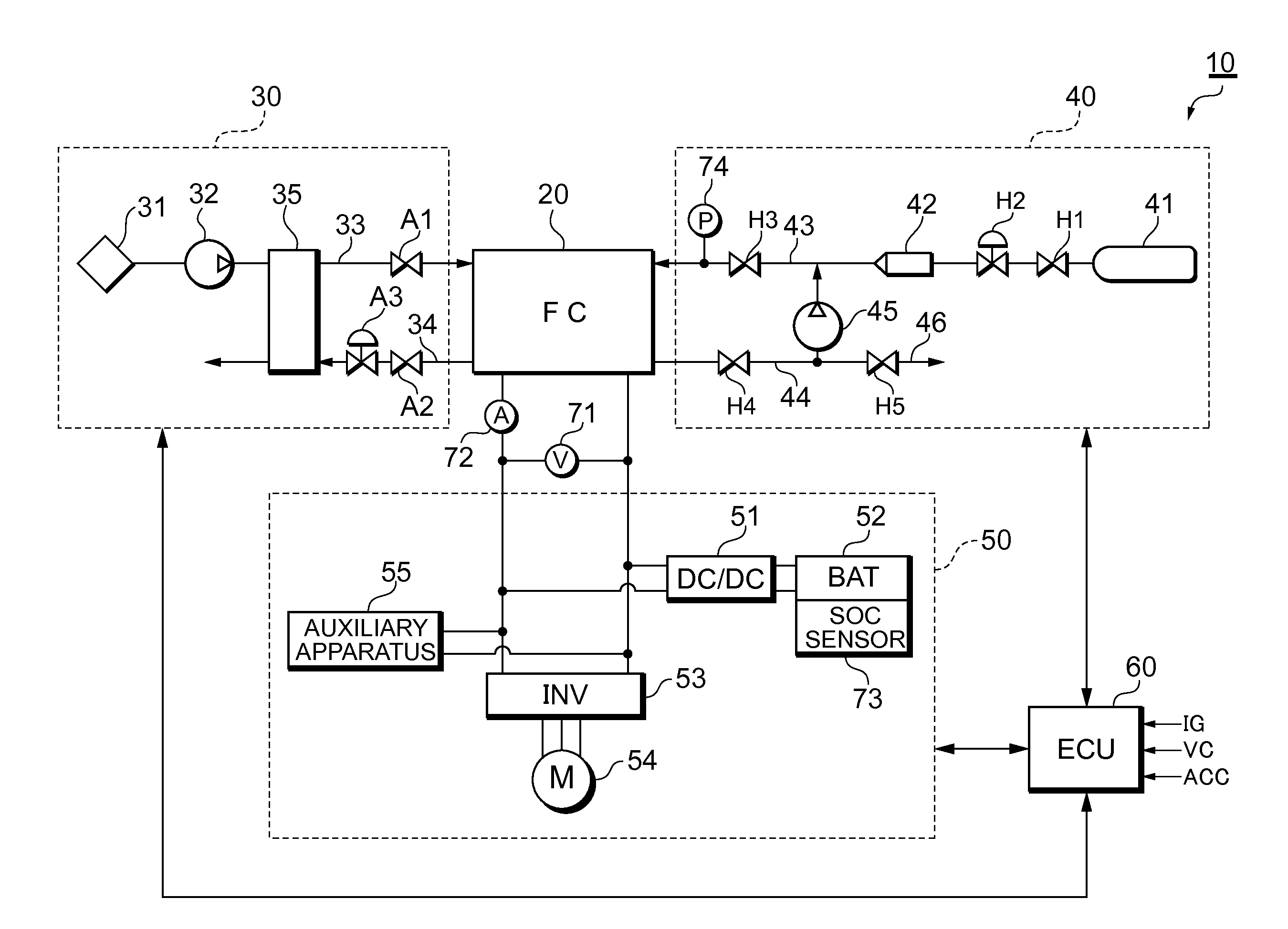
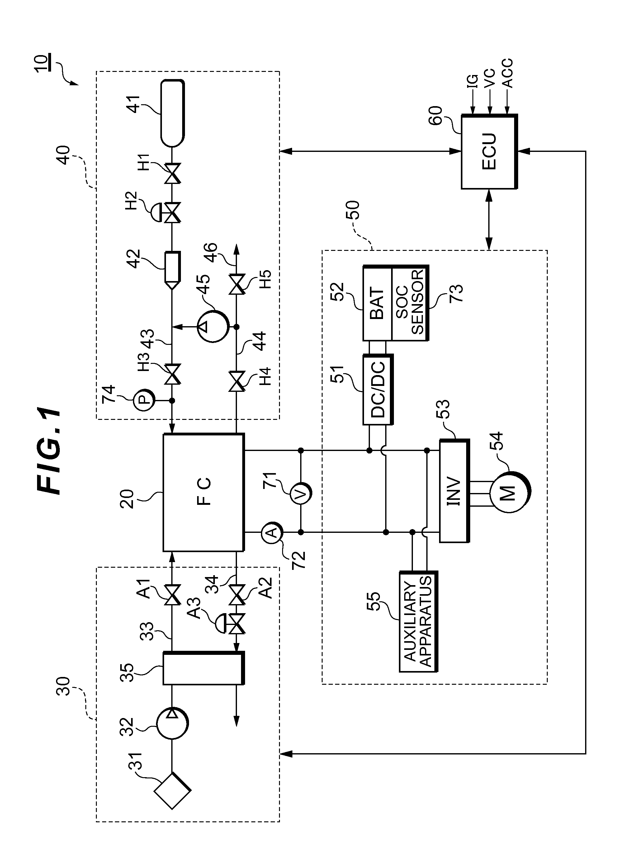
[0037]FIG. 1 illustrates the system configuration of a fuel cell system 10 according to an embodiment of the present invention.

[0038]The fuel cell system 10 serves as an in-vehicle power supply system that is installed in a fuel cell vehicle and includes: a fuel cell stack 20 which receives supply of reactant gases (a fuel gas and an oxidant gas) and generates electric power; an oxidant gas supply system 30 for supplying the air serving as the oxidant gas to the fuel cell stack 20; a fuel gas supply system 40 for supplying a hydrogen gas serving as the fuel gas to the fuel cell stack 20; a power system 50 for controlling charge and discharge of electric power; and a controller 60 which controls the entire system.

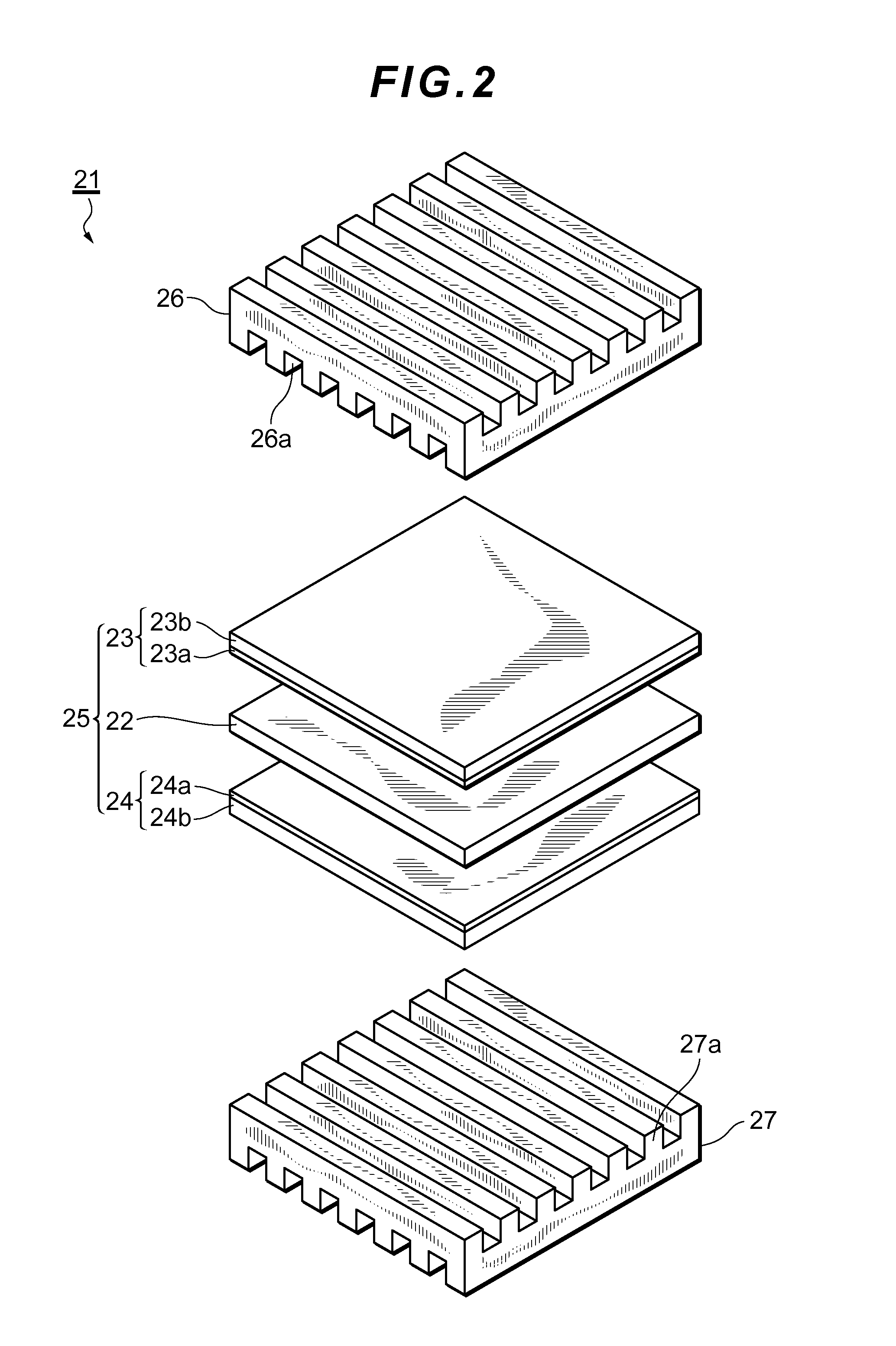
[0039]The fuel cell stack 20 is a solid polymer electrolyte-t...


PUM

PropertyMeasurementUnit
oxidation voltageaaaaaaaaaa
reduction voltageaaaaaaaaaa
output voltageaaaaaaaaaa

Abstract

A fuel cell system according to the present invention comprises: a fuel cell including a membrane-electrode assembly in which electrodes, each having a catalyst layer, are arranged on both surfaces of a polymer electrolyte membrane; a power storage apparatus connected to a load in parallel with the fuel cell; and a control apparatus that performs performance recovery processing for the catalyst layer by decreasing an output voltage of the fuel cell to a predetermined voltage, wherein an intermittent operation in which a power generation command value for the fuel cell is set to zero and a power supply to the load is covered by power supplied from the power storage apparatus is allowed to be performed if certain conditions for performing the intermittent operation are met, and the performance recovery processing is performed during the intermittent operation, and wherein, if the performance recovery processing is necessary and if a remaining power in the power storage apparatus is equal to or lower than a predetermined amount, the control apparatus delays a timing of performing the intermittent operation and charges the power storage apparatus until the remaining power exceeds the predetermined amount.

Description

TECHNICAL FIELD[0001]The present invention relates to a fuel cell system having a function of activating a catalyst.BACKGROUND ART[0002]A fuel cell stack is a power generation system which oxidizes a fuel through an electrochemical process to thereby directly convert energy released due to such oxidization reaction into electric energy. Such fuel cell stack has a membrane-electrode assembly in which a polymer electrolyte membrane, which selectively transports hydrogen ions, is sandwiched by a pair of electrodes made of porous materials. Each of the pair of electrodes includes: a catalyst layer that contains, as a main ingredient, carbon powder supporting a platinum-based metal catalyst and contacts with the polymer electrolyte membrane; and a gas diffusion layer formed on a surface of the catalyst layer, the gas diffusion layer having both air permeability and electronic conductivity.[0003]In fuel cell systems of this type, when a cell continues to be operated within an operation zo...

Claims


Application Information

Patent Timeline
Patent Type & Authority Applications(United States)
IPC IPC(8): H01M8/04
CPCH01M8/04611H01M2008/1095H01M8/04873H01M8/04238Y02E60/50
Inventor MATSUSUE, MASAAKIIKEDA, KOTAROINOUE, YUMI
Owner TOYOTA JIDOSHA KK
Why Eureka
Try Eureka