
Near Touch Interaction with Structured Light

a technology of structured light and interaction, applied in the field of near touch interaction with structured light, can solve the problems of unhygienic screen, multi-touch gesture responsiveness, and many problems of various single and multi-touch systems, and achieve the effect of improving the quality and consistency of depth maps and facilitating embedding

Active Publication Date: 2015-05-14
GOLDEN EDGE HLDG CORP
View PDF9 Cites 0 Cited by
  • Summary
  • Abstract
  • Description
  • Claims
  • Application Information

AI Technical Summary

Benefits of technology

This approach provides a reliable, efficient, and cost-effective near-touch system with enhanced depth map quality and responsiveness, suitable for real-time applications by minimizing entropy and computational requirements.

Problems solved by technology

The problems with various single and multi-touch systems are many.
Hygiene is another issue in which the screen, especially if used by more than one person, may become unhygienic.
Responsiveness that is associated with multi-touch gestures is another issue, since there exists a significant lag in the operation of the system itself.
There are no methods available today to reconstruct depth at such a close distance for real-time applications.
4 (December 2008): 589-600. however such methods are computationally expensive and lack robustness for them to be applicable to a tablet computer.
In addition to the fact that the light source is usually in the infrared range, and requires a significant amount of energy, active stereo suffers from a number of practical and computational drawbacks.
For instance, such methods are usually utilized to address depth computation at extremely large distances (relative to the screen, in the context of a few inches), forcing the light source to be very power-consuming and bulky.
The data from the depth images have to be evaluated over a number of frames, making the data sluggish and introducing a significant amount of motion blur and computational artifacts that become apparent in performance.
Such methods are inappropriate for near-touch interaction.

Method used


Image

  • Near Touch Interaction with Structured Light
  • Near Touch Interaction with Structured Light
  • Near Touch Interaction with Structured Light

Examples


Embodiment Construction

[0018]One or more embodiments of the invention will now be described, making reference to the following drawings in which like reference numbers indicate like structure between the drawings.

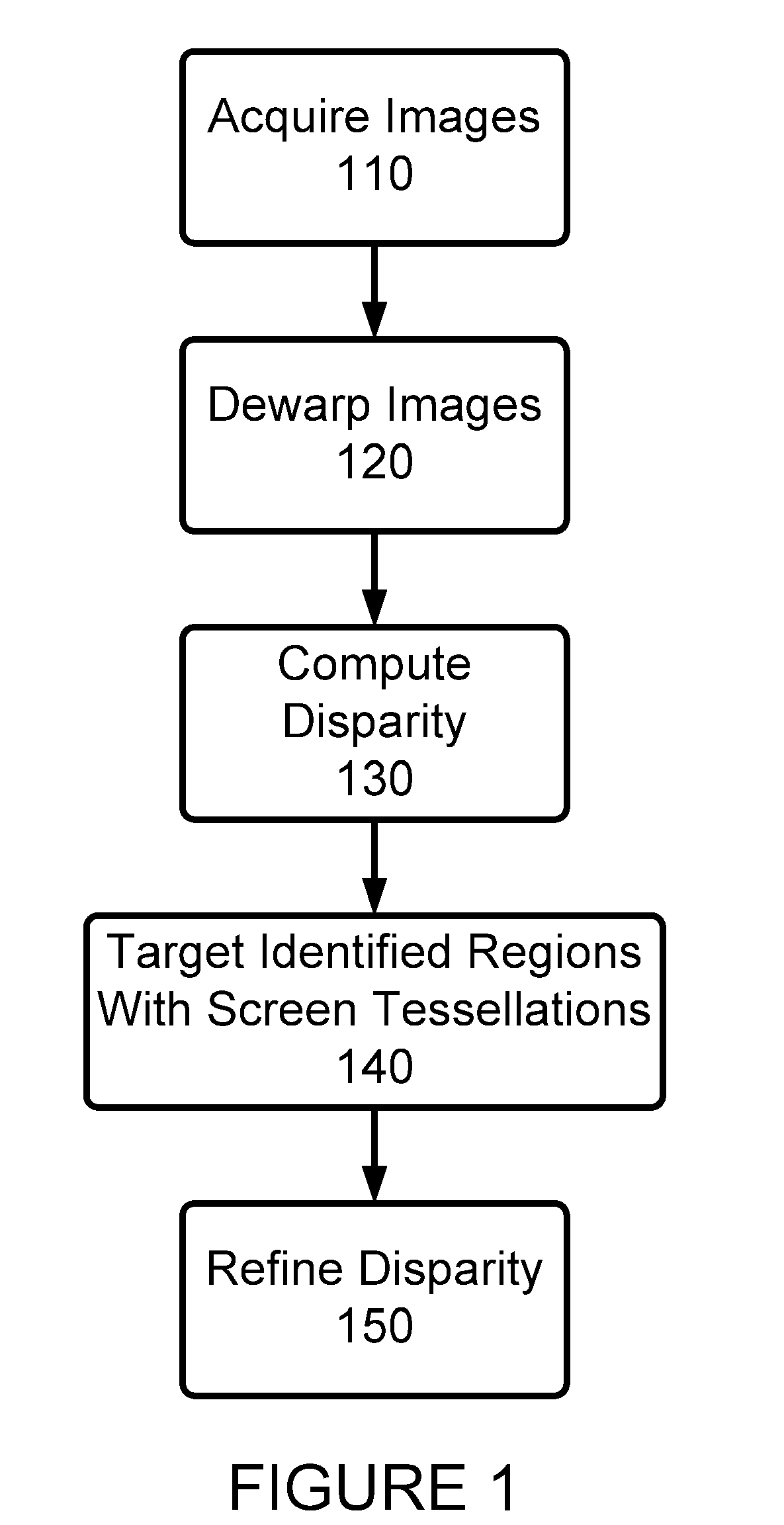
[0019]An overview of a preferred approach in accordance with an embodiment of the present invention is shown in FIG. 1. As is shown in FIG. 1, at step 110 one or more images are acquired, and then at step 120, these images may be dewarped if desired or determined necessary or advantageous. A disparity is computed at step 130, and at step 140 target regions may be identified and illuminated with screen tessellations. Finally, at step 150, disparity is refined.

[0020]In accordance with one or more embodiments of the present invention, wide angle lenses are preferably utilized. Such wide angle lenses allow for a wide field of view to be acquired, allow for the viewing of objects close to the cameras, and thus the display, and also produce a shallow depth of field, thus blurring a background or other ...


PUM


Abstract

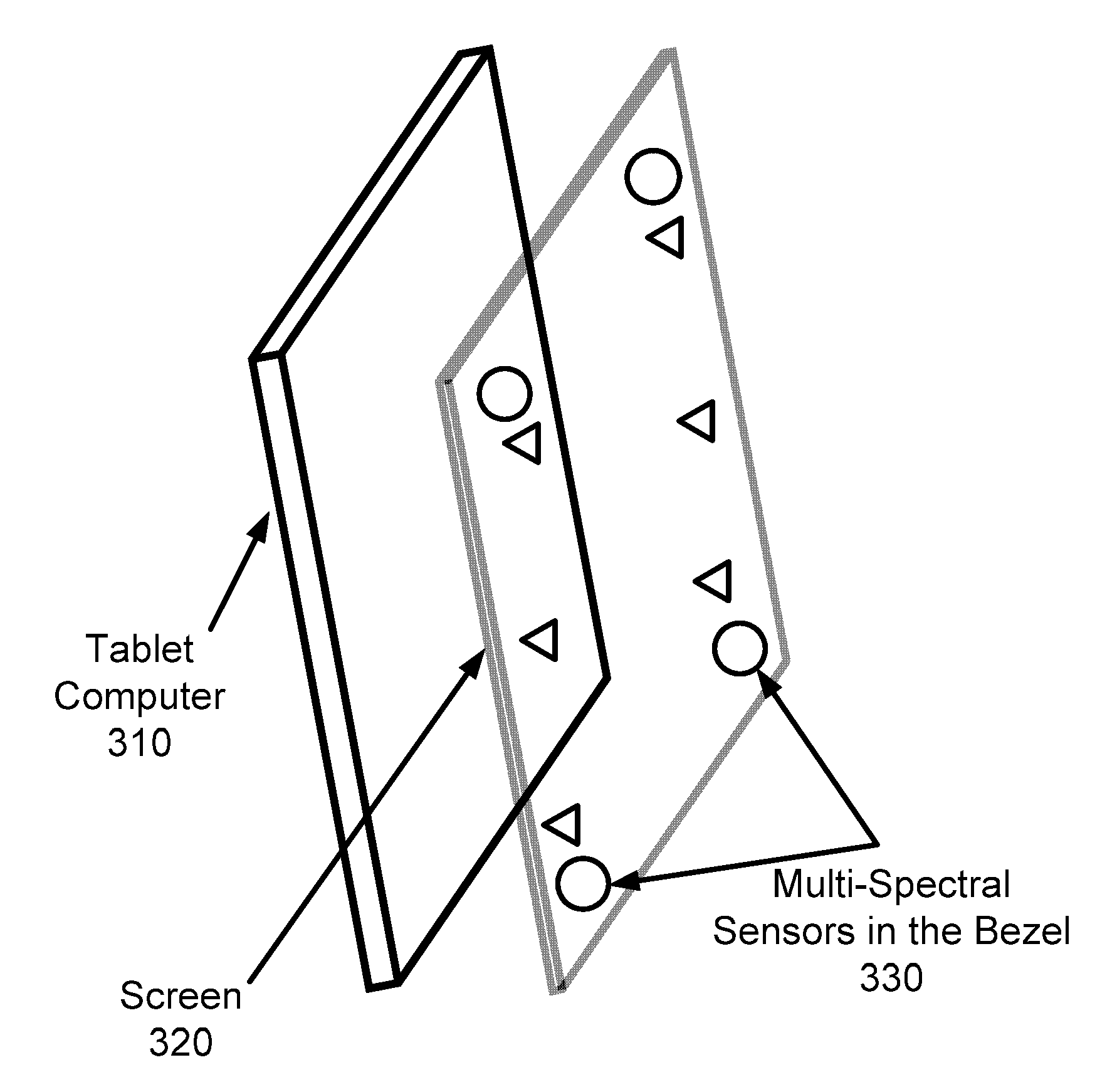
A near-touch interface is provided that utilizes stereo cameras and a series of targeted structured light tessellations, emanating from the screen as a light source and incident on objects in the field-of-view. After radial distortion from a series of wide-angle lenses is mitigated, a surface-based spatio-temporal stereo algorithm is utilized to estimate initial depth values. Once these values are calculated, a subsequent refinement step may be applied in which light source tessellations are used to flash a structure onto targeted components of the scene, where initial near-interaction disparity values have been calculated. The combination of a spherical stereo algorithm, and smoothing with structured light source tessellations, provides for a very reliable and fast near-field depth engine, and resolves issues that are associated with depth estimates for embedded solutions of this approach.

Description

CROSS REFERENCE TO RELATED APPLICATIONS[0001]This application is a continuation of U.S. patent application Ser. No. 13 / 189,517 filed Jul. 24, 2011, titled “Near-Touch Interaction with a Stereo Camera Grid and Structured Tesellations” to El Dokor, which in turn claims the benefit of U.S. Provisional Patent Application Ser. No. 61 / 441,630 filed Feb. 10, 2011, titled “Near-Touch Interaction with a Stereo Camera Grid and Structured Tessellations” to El Dokor, the contents of each of these applications being incorporated herein by reference.BACKGROUND OF THE INVENTION[0002]Multi-touch technology has become a standard modus of interaction with new touch screens. Such screens are becoming more pervasive, making their way into mobile technology and allowing for evolving forms of interaction. Such touch screen technology has enabled a shift in computing into a new brand of devices, including tablet computers, mobile devices and other touch screen supported systems. The problems with various ...

Claims


Application Information

Patent Timeline
Patent Type & Authority Applications(United States)
IPC IPC(8): G06F3/042G06T7/00
CPCG06F3/0421G06T7/0057G06T2207/10021G06F2203/04104G06T2200/04G06F2203/04108G06T7/521G06T7/593
Inventor EL DOKOR, TAREK
Owner GOLDEN EDGE HLDG CORP
Learn More