Wavelength Stabilized Diode Laser

Active Publication Date: 2015-05-14
INNOVATIVE PHOTONIC SOLUTIONS INC
View PDF7 Cites 6 Cited by
  • Summary
  • Abstract
  • Description
  • Claims
  • Application Information

AI Technical Summary

Benefits of technology

[0030]Briefly, to achieve the desired objects of the present invention in accordance with a preferred embodiment, disclosed is a hybrid external cavity laser with enhanced wavelength stability. The hybrid external cavity laser utilizes a VBG as a reflector and output coupler, with specific reflectivity optimized to enhance wavelength stability of the device. In conjunction with a semiconductor gain section which also has specific reflectivities, multiple cavities are formed within the hybrid external cavity laser device. Only when the resonances of the multiple cavities are aligned does the device act as a laser, assuring stable single mode operation. Wavelength stability is further enhanced by adjusting the reflectance profile of the VBG so that its peak substantially coincides with resonance peaks of the multiple cavities formed within the device. The resonances are aligned by adjusting the position of the VBG and/or the temperature of the individual cavities. As the VBG is fabricated in glass, which has a low thermal coefficient of expansion, the properties of the Bragg grating are quite stable with temperature. In addition, the optical components are mounted on a low coefficient of expansion platform, typically formed from silicon or ceramic. Thus the external cavity length is stable with temperature, further improving the wavelength stability of the device described herein. These factors combine to form a hybrid external cavity laser that operates in a single mode with narrow linewidth and exceptional wavelength stability, even at high output powers.
[0031]The devices and methods disclosed herein differ from prior art related to external cavity wavelength stabilized semiconductor lasers in that the prior art uses a semiconductor laser and an external cavity that provides a wavelength narrowing seed to force the semiconductor la

Problems solved by technology

Additionally, the reflectivity of the VBG is chosen such that feedback from the grating is insufficient on its own to support operation of the HECL device.
Thus the HECL device ca

Method used


Image

  • Wavelength Stabilized Diode Laser
  • Wavelength Stabilized Diode Laser
  • Wavelength Stabilized Diode Laser

Examples


Embodiment Construction

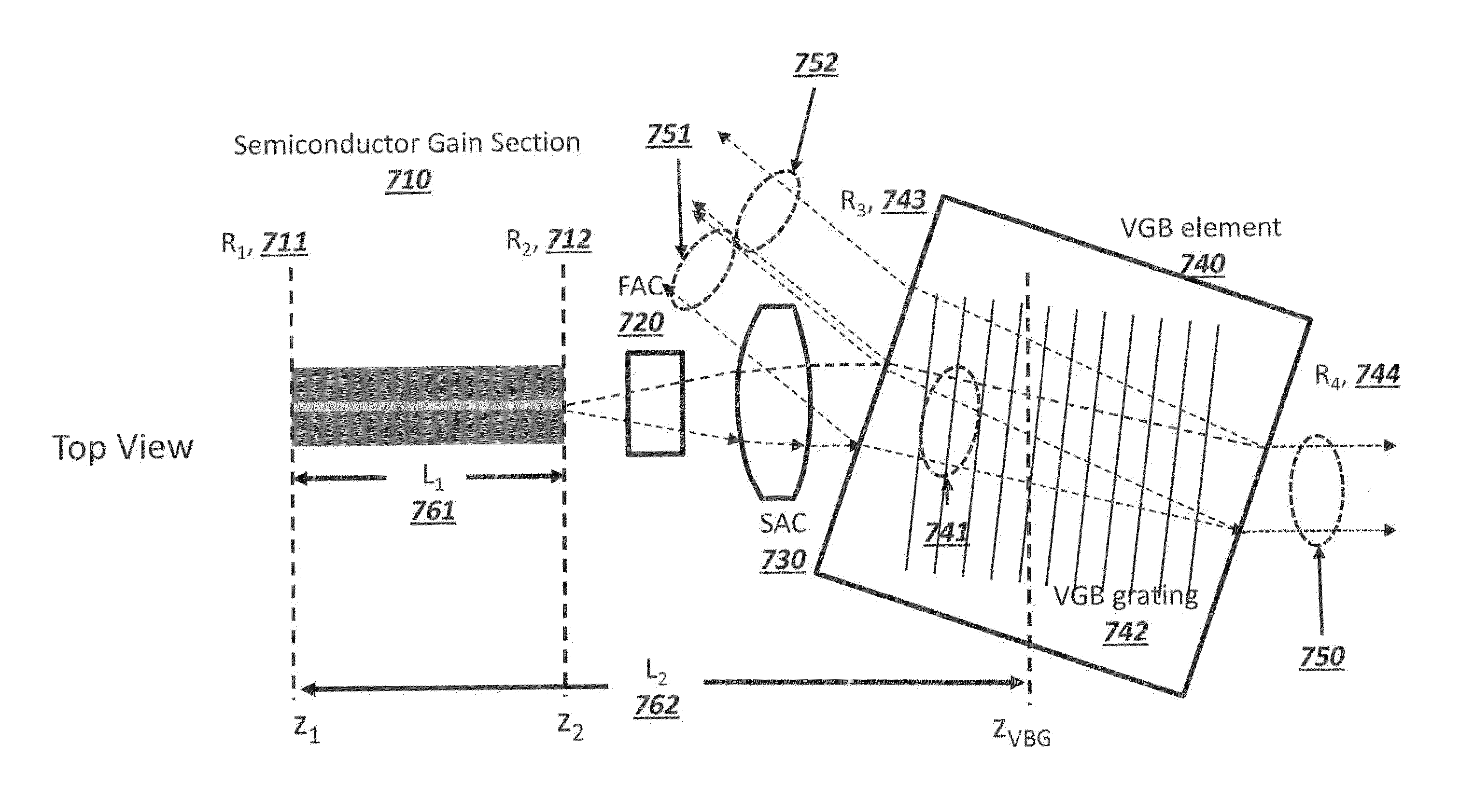
[0050]Stable single-longitudinal mode operation of a HECL Laser has been achieved by utilizing a semiconductor gain section in which lasing is prevented by choosing a combination of low front facet reflectivity and cavity length such that the semiconductor gain is insufficient to offset the loss of light through the low reflectivity front facet. That is, without feedback from the VBG, the semiconductor gain section operates in a non-lasing mode (i.e., superluminescent diode). In addition, the reflectivity of the VBG is chosen such that the HECL laser also will not lase in the absence of some feedback from the front facet of the semiconductor gain section. Thus, in order for the HECL to operate as a laser, the reflected emission from both the front facet and VBG must resonantly combine to reach lasing threshold. This leads to stable single longitudinal mode operation of the HECL embodied herein.

[0051]To achieve the necessary resonance of the reflected emissions, the resonant frequenc...


PUM


Abstract

A hybrid external cavity laser and a method for configuring the laser having a stabilized wavelength is disclosed. The laser comprises a semiconductor gain section and a volume Bragg grating, wherein a laser emission from the semiconductor gain section is based on a combination of a reflectivity of a front facet of the semiconductor gain section and a reflectivity of the volume Bragg grating and the reflectivity of the semiconductor gain section and the volume Bragg grating are insufficient by themselves to support the laser emission. The hybrid cavity laser further comprises an etalon that provides further wavelength stability.

Description

CLAIM OF PRIORITY[0001]This application claims, pursuant to 35 USC 120, priority to, and the benefit of the earlier filing date of, that patent application, entitled “Wavelength Stabilized Diode Laser, filed on Dec. 3, 2013 and afforded Ser. No. 14 / 094,790, which claimed, pursuant to 35 USC 119, priority to, and the benefit of the earlier filing date of, that provisional patent application, entitled “Wavelength Stabilized Diode Laser,” filed on Nov. 13, 2013 and afforded Ser. No. 61 / 903,942, the contents of all of which are incorporated by reference, herein.FIELD OF THE INVENTION[0002]This invention relates to the field of diode lasers and more particularly to a stable single mode operation of semiconductor diode lasers.BACKGROUND OF THE INVENTION[0003]Relative to other laser designs, diode lasers are more compact and robust, less expensive, electrically more efficient, radiate less waste heat, and easier to use as they do not require long warm-up times or great amounts of power (e....

Claims


Application Information

Patent Timeline
IPC IPC(8): H01S5/12H01S5/14
CPCH01S5/14H01S5/12H01S3/08027H01S5/02438H01S5/0287H01S5/0654H01S5/1039H01S5/141H01S2301/02
Inventor CONNOLLY, JOHN C.ACKLEY, DONALD ERUDDER, SCOTT L.GUENTHER, HARALD R.
Owner INNOVATIVE PHOTONIC SOLUTIONS INC
Why Eureka
Try Eureka