
Wavelength conversion devices and fabrication methods for same

a conversion device and wavelength technology, applied in the direction of laser details, instruments, light demodulation, etc., can solve the problems of back reflection, unwanted bragg grating, and unstable wavelength of dbr lasers, so as to increase the stability of semiconductor laser wavelengths and minimize back reflections

Inactive Publication Date: 2008-08-19
CORNING INC
View PDF6 Cites 6 Cited by
  • Summary
  • Abstract
  • Description
  • Claims
  • Application Information

AI Technical Summary

Benefits of technology

[0003]The present inventors have found that back reflections coming from the wavelength conversion device and re-injected into the semiconductor laser play a key role for wavelength stability. Lasers such as DBR lasers are very sensitive to feedback and can become unstable in wavelength with feedback levels as low as −60 to −70 dB. For example, Bragg gratings may cause back reflections in a laser system. The present inventors have also found that, although a wavelength conversion device such as an SHG crystal may not intentionally comprise Bragg gratings in a DFB laser system, the bulk of the SHG crystal presents some periodic or nearly periodic features such as the crystal poling or other features associated with the way that the crystal waveguide is made. These features may act like unwanted Bragg gratings and generate some significant feedback to the laser diode.
[0004]Given the challenges associated with wavelength matching and stabilization in developing semiconductor laser sources, the present inventors have recognized a method to fabricate a wavelength conversion device to minimize back reflections from the wavelength conversion device to a semiconductor laser, thereby increasing semiconductor laser wavelength stability.

Problems solved by technology

Lasers such as DBR lasers are very sensitive to feedback and can become unstable in wavelength with feedback levels as low as −60 to −70 dB.
For example, Bragg gratings may cause back reflections in a laser system.
These features may act like unwanted Bragg gratings and generate some significant feedback to the laser diode.

Method used


Image

  • Wavelength conversion devices and fabrication methods for same
  • Wavelength conversion devices and fabrication methods for same
  • Wavelength conversion devices and fabrication methods for same

Examples


Embodiment Construction

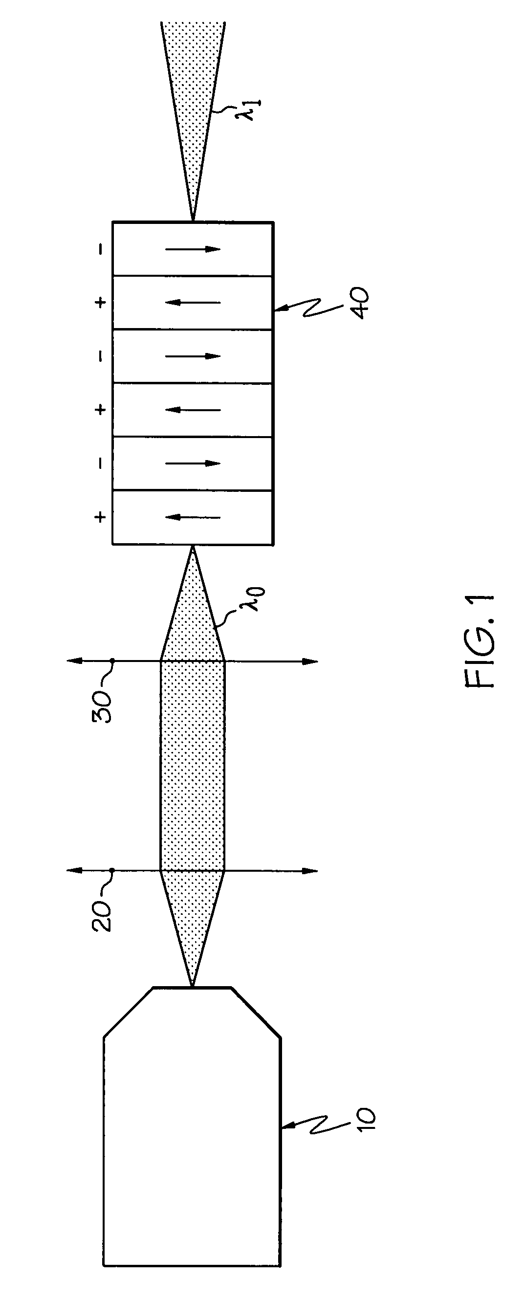
[0011]In FIG. 1, the DBR laser 10 is optically coupled to a light wavelength conversion device 40 comprising a nonlinear optical material. As will be appreciated by those familiar with laser design, DFB lasers are resonant-cavity lasers using grids or similar structures etched into the semiconductor material as a reflective medium. DBR lasers are lasers in which the etched Bragg grating is physically separated from the electronic pumping area of the semiconductor laser. On the other hand, a Fabry-Perot laser has no wavelength selective section and, therefore generates multiple wavelengths. To operate the Fabry-Perot laser in single mode, it is therefore necessary to introduce a wavelength selective component into the optical path to reflect some light towards the diode and stabilize the wavelength. This function can be achieved by integrating a Bragg grating over a portion of a periodically poled lithium niobate (PPLN) crystal waveguide. It is contemplated that these and other types...


PUM

PropertyMeasurementUnit
Bragg wavelength λBRAGGaaaaaaaaaa
phasematching wavelength λΦaaaaaaaaaa
Bragg wavelengthaaaaaaaaaa

Abstract

Particular embodiments of the present invention relate generally to a method of fabricating a wavelength conversion device. According to the method, the wavelength conversion device is fabricated by providing a nonlinear optical material and poling the nonlinear optical material to form a plurality of periodically inverted poling domains arranged at an anti-back reflective periodicity Λ. The geometry and the anti-back reflective periodicity Λ of the poled nonlinear material are selected such that the difference between a phase matching wavelength λΦ of the poled nonlinear optical material and a Bragg wavelength λBRAGG of the poled nonlinear optical material is greater than 1 nm.

Description

BACKGROUND OF THE INVENTION[0001]The present invention relates generally to wavelength conversion devices and fabrication methods of the same. More particularly, some embodiments of the present invention relate to a fabrication method for a wavelength conversion device that introduces a poling period within the wavelength conversion device such that the wavelength of the phase matching signal is sufficiently different than the Bragg wavelength.SUMMARY OF THE INVENTION[0002]The present invention relates generally to wavelength conversion devices, such as second harmonic generation crystals (SHG), which may be usefully configured with semiconductor lasers in a variety of ways. For example and by way of illustration, not limitation, short wavelength sources can be configured for high-speed modulation by combining a single-wavelength semiconductor laser, such as a distributed feedback (DFB) laser, a distributed Bragg reflector (DBR) laser, a vertical cavity surface-emitting laser (VCSEL...

Claims


Application Information

Patent Timeline
Patent Type & Authority Patents(United States)
IPC IPC(8): G02F1/35H01S3/10
CPCG02F1/3775G02F1/3558G02F2201/307H01S5/0064
Inventor GOLLIER, JACQUESPIECH, GARRETT ANDREW
Owner CORNING INC
Learn More