Glazing unit with antenna unit

a technology of antenna unit and glazing unit, which is applied in the structure of radiating element, antenna equipment with additional functions, disturbance protection, etc., can solve the problems of thermal cracking in the first layer of permeable member, excessive rise of the temperature of the first layer, etc., and reduce the possibility of thermal cracking. , the effect of reducing the reflection of the wave radiated

Pending Publication Date: 2022-04-07
AGC GLASS EUROPE SA +3
View PDF1 Cites 0 Cited by
  • Summary
  • Abstract
  • Description
  • Claims
  • Application Information

AI Technical Summary

Benefits of technology

[0008]It is an object of the present invention to alleviate these problems, and to provide a glazing unit which reduces the reflection of the waves radiated by the antenna from the glass panel while reducing the possibility of occurrence of thermal cracking in the glass panel.
[0019]In some preferred embodiment, the largest dimension of the every hole of every metallic element further is at most 0.4 times the effective wavelength to minimize back reflection.
[0023]In some more preferred embodiments, the glass panel comprises a coating layers system to improve the thermal insulation of the glazing unit.

Problems solved by technology

However, according to the technique described in JP06196915, there is a case where the temperature of the first layer excessively rises when the sunlight hits the first layer, depending on the installation place or the installation condition of the antenna unit and the like, It has not been studied that there is a possibility of thermal cracking in the first layer of the permeable member.

Method used


Image

  • Glazing unit with antenna unit
  • Glazing unit with antenna unit
  • Glazing unit with antenna unit

Examples


Embodiment Construction

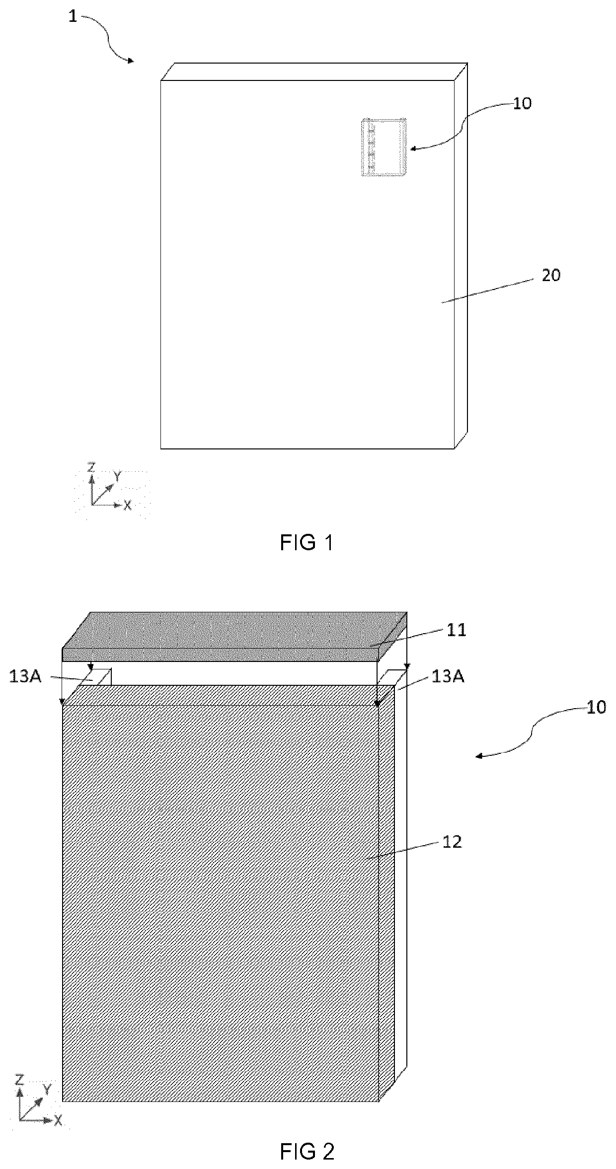
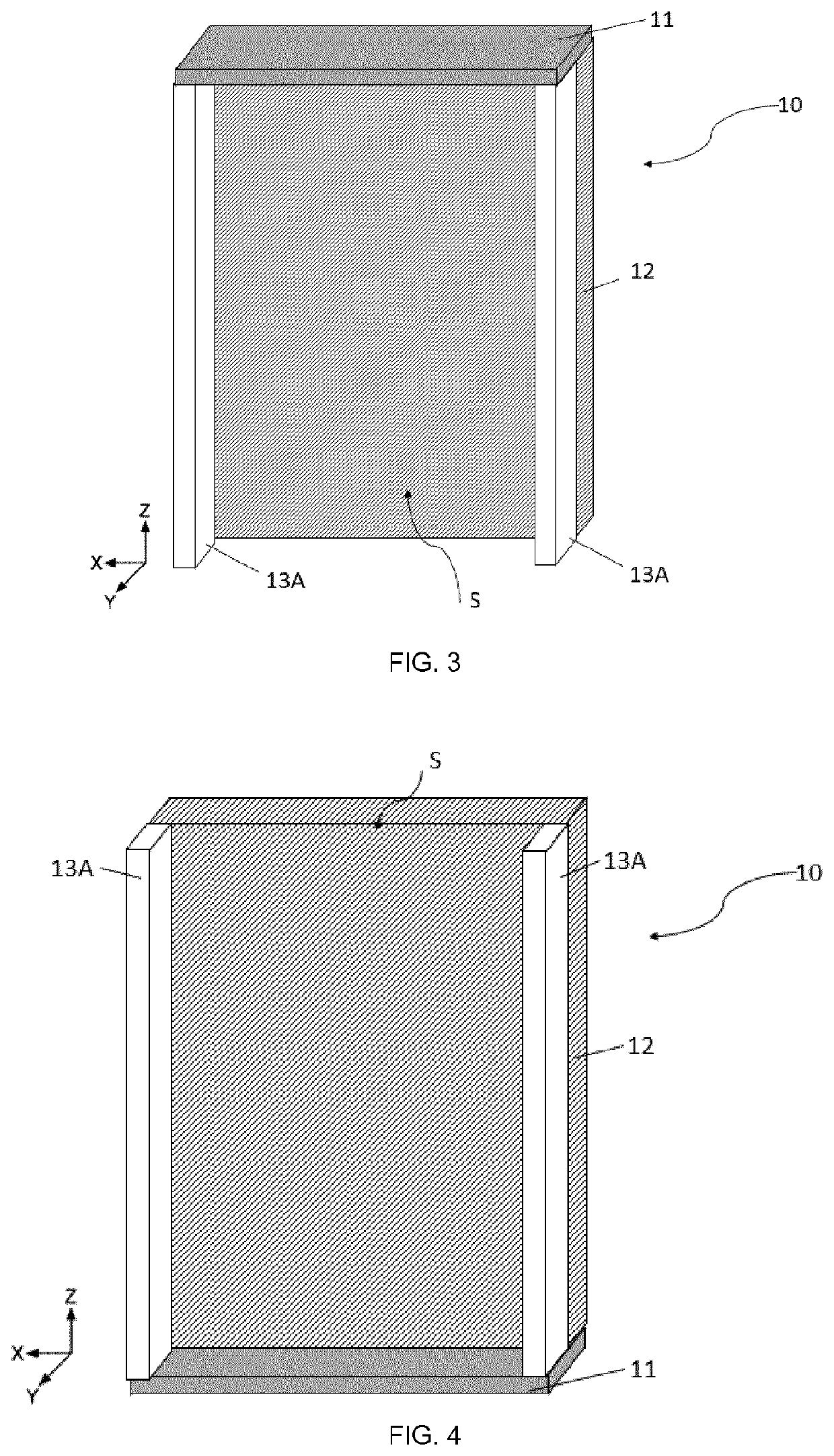
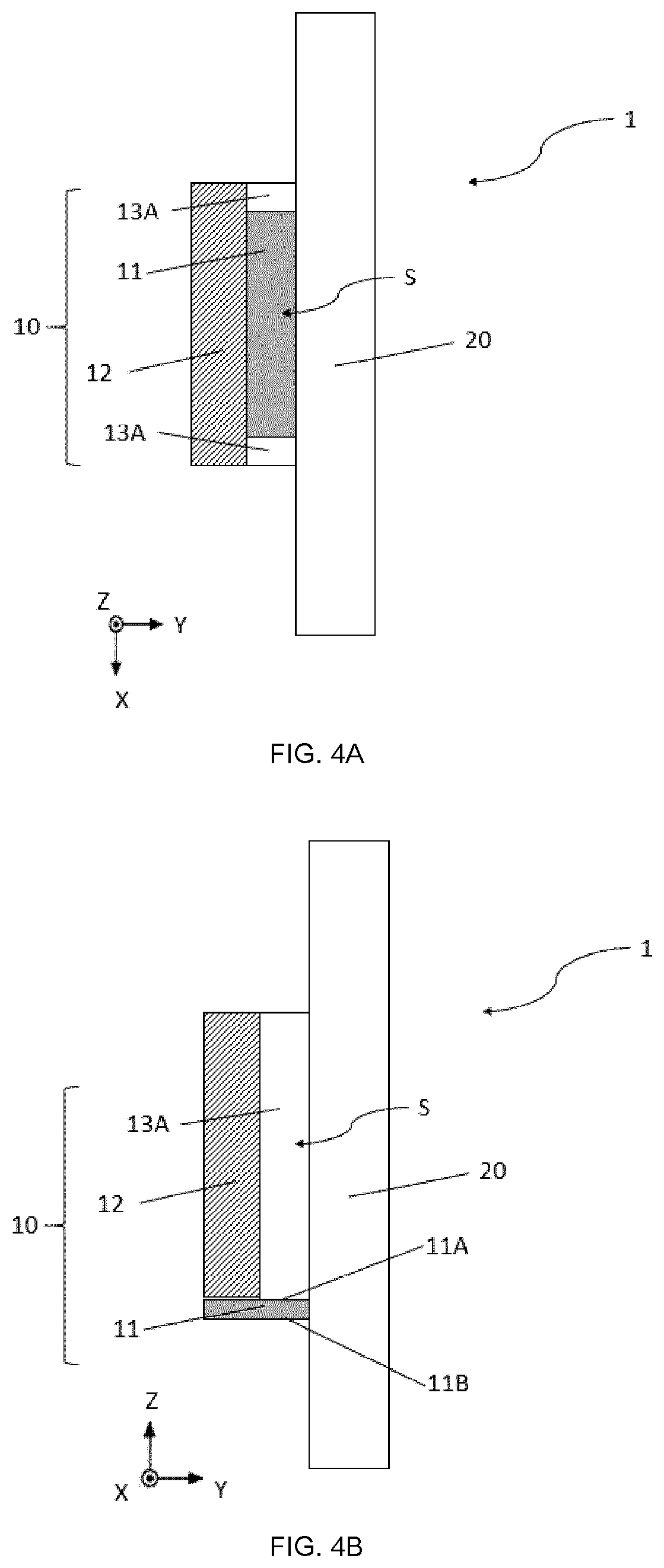
[0045]For a better understanding, the scale of each member in the drawing may be different from the actual scale. In the present specification, a three-dimensional orthogonal coordinate system in three axial directions (X axis direction, Y axis direction, Z axis direction) is used, the width direction of the glass panel is defined as the X direction, the thickness direction is defined as the Y direction, and the height is defined as the Z direction. The direction from the bottom to the top of the glass panel is defined as the +Z axis direction, and the opposite direction is defined as the −Z axis direction. In the following description, the +Z axis direction is referred to as upward and the −Z axial direction may be referred to as down.

[0046]With reference to FIG. 1, a first embodiment of the present invention is described.

[0047]As shown in FIG. 1, a glazing unit 1 extending along a plane, P, defined by a longitudinal axis, X, and a vertical axis, Z; having a width, W, measured alon...


PUM


Abstract

A glazing unit extends along a plane, P, defined by a longitudinal axis, X, and a vertical axis, Z; having a width, W, measured along the longitudinal axis, X, and a length, L, measured along the vertical axis, Z, and includes at least a glass panel and an antenna unit. The antenna unit includes an antenna. The antenna unit also includes a fixing portion for fixing the antenna to the glass panel so that a space, S, through which air can flow is formed between the glass panel and the antenna. At least one non-fixing portion and at least one metallic element are placed over at least a part of the non-fixing portion of the antenna unit.

Description

TECHNICAL FIELD[0001]The present invention relates to a glazing unit with an improved antenna unit.BACKGROUND ART[0002]Various communication systems based on wireless technologies such as cellular communication, radio broadcasting, GPS (Global Positioning System) are being developed. In order to deal with these communication systems, an antenna capable of transmitting and receiving electromagnetic waves used for each communication system is required.[0003]In recent years, with miniaturization, antennas are increasingly installed in buildings. A large number of antennas are installed in the building so that electromagnetic waves used for mobile communications can be transmitted and received in a stable manner. When installing the antenna in the building, it is necessary to select the proper placement of the antenna so that electromagnetic waves can be transmitted and received stably while preventing the appearance of the building from being impaired.[0004]In addition, in order to inc...

Claims


Application Information

Patent Timeline
Patent Type & Authority Applications(United States)
IPC IPC(8): H01Q1/00H01Q1/12H01Q1/02
CPCH01Q1/002H01Q1/02H01Q1/1271H01Q1/007H01Q1/38H01Q1/44
Inventor YOUSEFBEIKI, MOHSEN
Owner AGC GLASS EUROPE SA
Why Eureka
Try Eureka