
Medical apparatus for heating a heating volume defined by a surface

Inactive Publication Date: 2015-05-14
KONINKLJIJKE PHILIPS NV
View PDF3 Cites 6 Cited by
  • Summary
  • Abstract
  • Description
  • Claims
  • Application Information

AI Technical Summary

Benefits of technology

The invention is about a method of using ultrasound to treat pain. By controlling the transducer elements to emit a beam that matches the size of the affected area, the ultrasound energy density can be increased to induce a therapeutic effect. The goal is to create a treatment plan that targets the affected area with high accuracy. In addition, the invention also includes a method to use magnetic resonance imaging to monitor the heating of the area. This can help adjust the intensity of the ultrasound treatment and ensure safe and effective treatment. Overall, the invention allows for a more targeted and effective treatment for pain.

Problems solved by technology

The ultrasonic waves from each of the transducer elements either add constructively or destructively.
Patients suffering from bone cancers may find it extremely difficult to remain still during a long procedure.

Method used


Image

  • Medical apparatus for heating a heating volume defined by a surface
  • Medical apparatus for heating a heating volume defined by a surface
  • Medical apparatus for heating a heating volume defined by a surface

Examples


Embodiment Construction

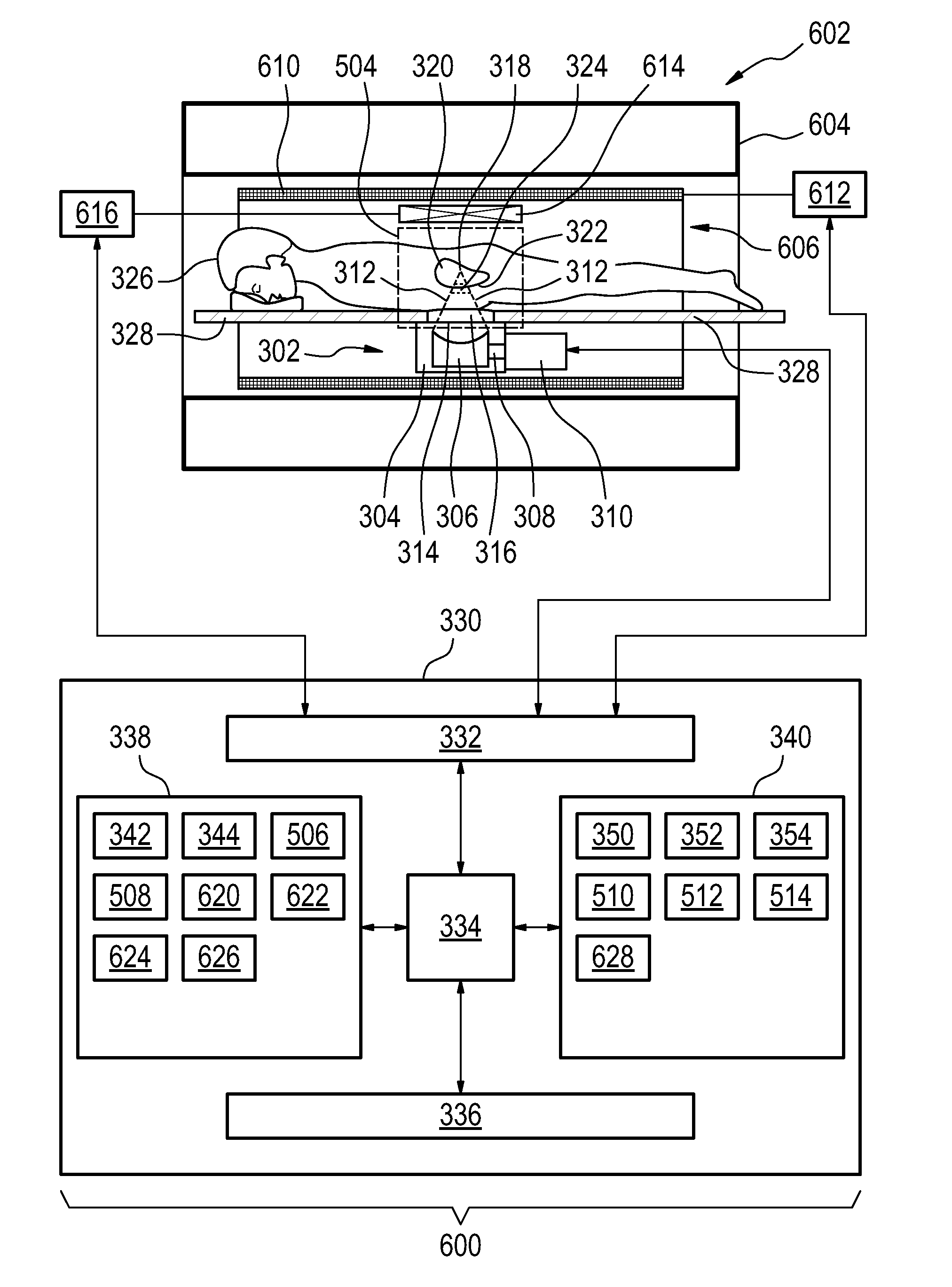
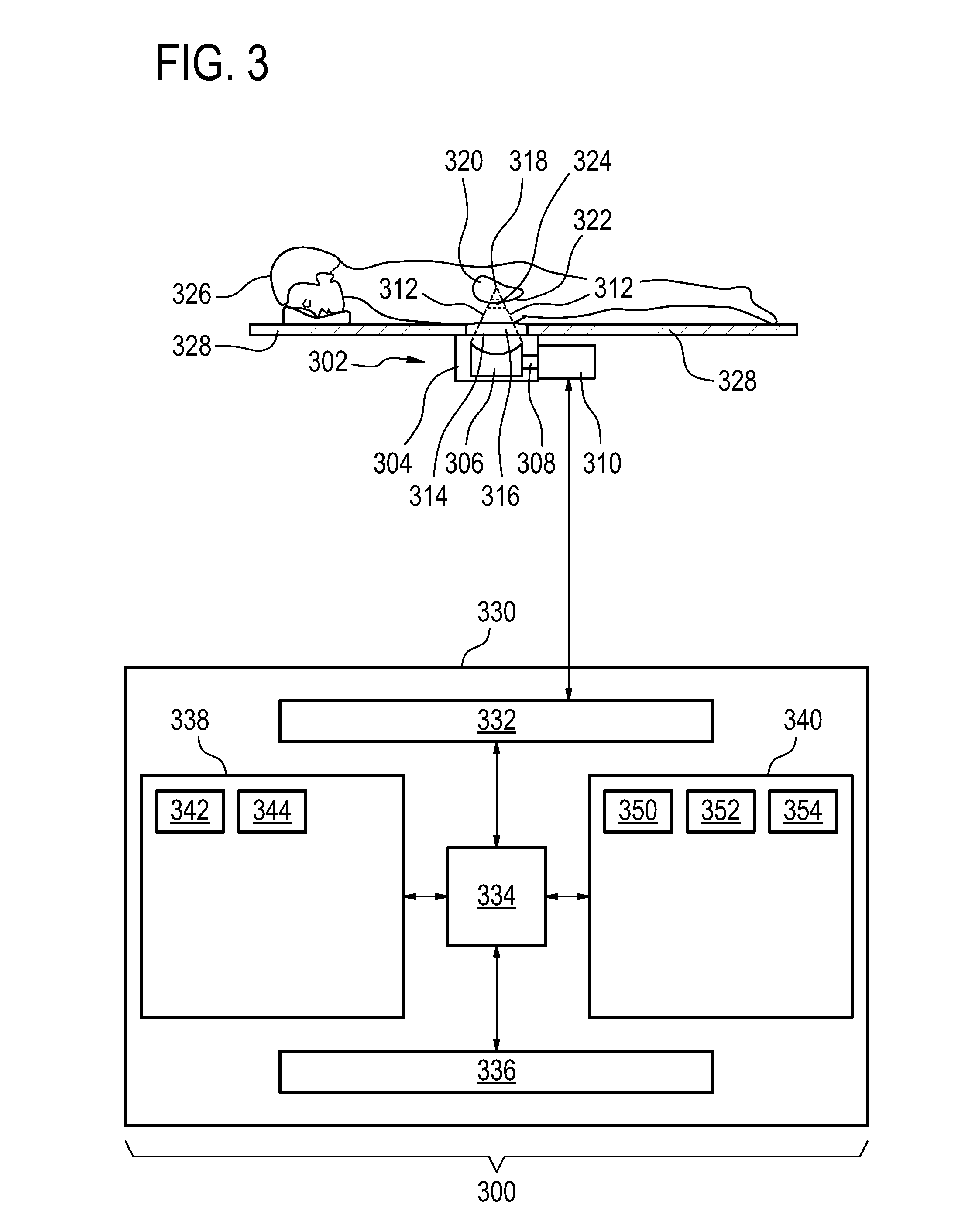
[0074]Like numbered elements in these figures are either equivalent elements or perform the same function. Elements which have been discussed previously will not necessarily be discussed in later figures if the function is equivalent.

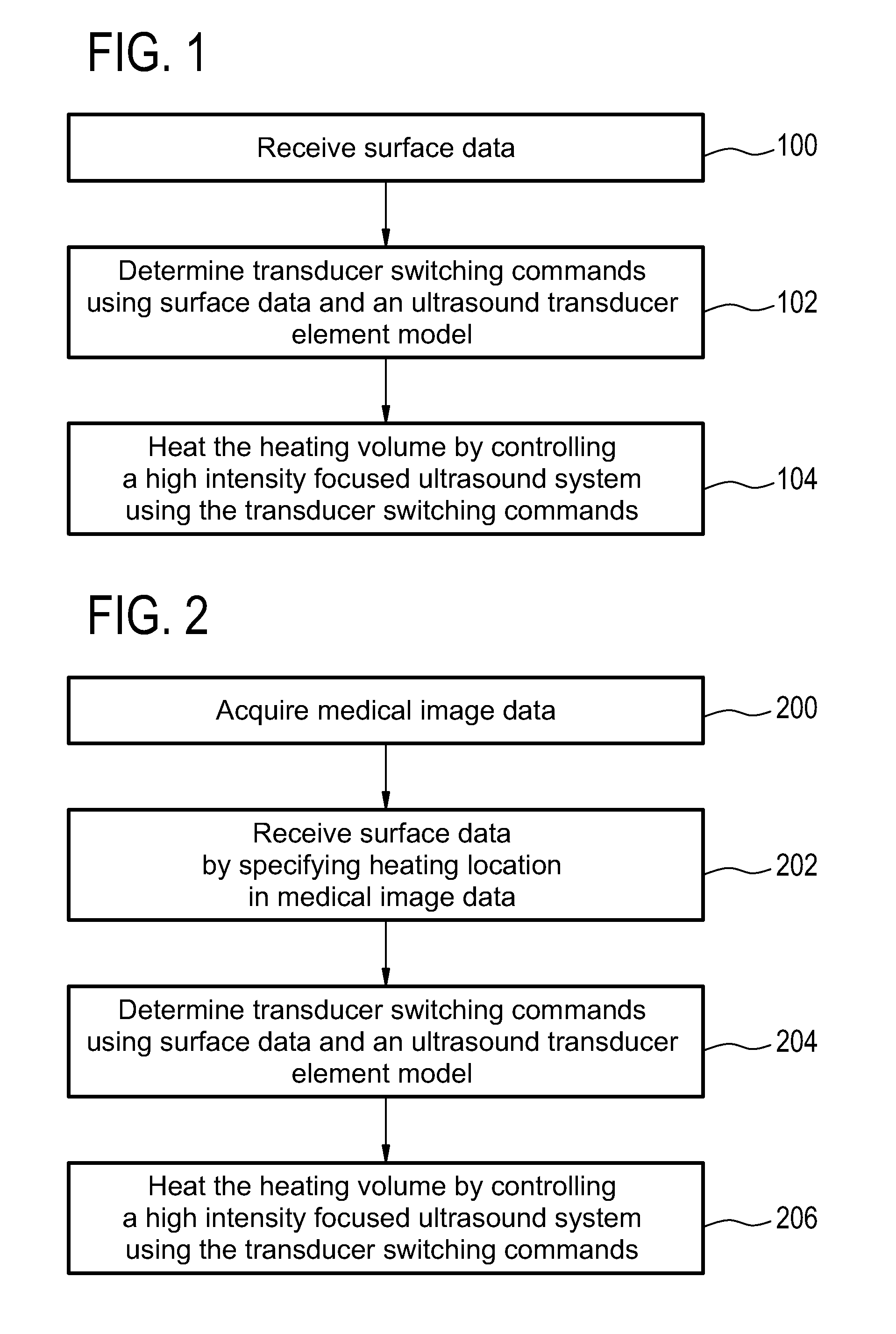
[0075]FIG. 1 shows a flow diagram which illustrates a method according to an embodiment of the invention. In step 100 surface data is received. Next in step 102 transducer-switching commands for ultrasound transducer elements are determined using the surface data and an ultrasound transducer element model. Finally in step 104 the heating volume is heated by controlling a high-intensity focused ultrasound system using the transducer-switching commands.

[0076]FIG. 2 shows a flow diagram which illustrates a method according to a further embodiment of the invention. First in step 200 medical image data is acquired. Next in step 202 surface data is received by specifying the heating location in the medical image data. This step may include constructing a medi...


PUM


Abstract

The invention provides for a medical apparatus (300, 500, 600) comprising a high intensity focused ultrasound system (302), a memory containing instructions, and a processor. Execution of the instructions causes the processor to receive (100,202) surface data (342) descriptive of the location of a surface (322). The surface data defines the location of the heating volume. Execution of the instructions further cause the processor to determine (102, 204) a set of transducer switching commands (344) using the heating location data and an ultrasound transducer element model (352) and control (104, 206) the high intensity focused ultrasound system with the set of transducer switching commands to heat the heating volume. The set of transducer switching commands comprises an intensity level for the multiple ultrasound transducer elements either above or below a predetermined intensity for controlling a cross sectional shape of the heating volume to encompass the surface.

Description

TECHNICAL FIELD[0001]The invention relates to high intensity focused ultrasound, in particular to the heating of a volume specified by a surface.BACKGROUND OF THE INVENTION[0002]In high intensity focused ultrasound (HIFU) an array of ultrasonic transducer elements are used to form an ultrasonic transducer. Supplying alternating current electrical power to the transducer elements causes them to generate ultrasonic waves. The ultrasonic waves from each of the transducer elements either add constructively or destructively. By controlling the phase of alternating current electrical power supplied to each of the transducer elements the focal point or volume into which the ultrasound power is focused may be controlled.[0003]To ease the pain and suffering of some cancer patients, HIFU bone therapy has been used to destroy nerves on a restricted bone surface area. Current HIFU bone therapy applications work by placing cells or sonication points of various sizes either on the bone surface or...

Claims


Application Information

Patent Timeline
IPC IPC(8): A61N7/02
CPCA61N7/02
Inventor VIITALA, ANTTI JOHANNESYLIHAUTALA, MIKA PETRI
Owner KONINKLJIJKE PHILIPS NV
Learn More