Plunger lift optimization

a technology of optimizing and optimizing the oil production field, applied in the direction of positive displacement liquid engine, survey, borehole/well accessories, etc., can solve the problems of not providing the actual details needed to optimize the plunger lift control in various conditions, and addressing what optimization looks like, so as to minimize the pressure of the bottom hole, maximize the production rate, and save time and cost.

Active Publication Date: 2015-05-21
CONOCOPHILLIPS CO
View PDF3 Cites 39 Cited by
  • Summary
  • Abstract
  • Description
  • Claims
  • Application Information

AI Technical Summary

Benefits of technology

[0022]The new logic described herein eliminates the need for continual human intervention and potential misinterpretations of plunger optimization principles, as those principles relate to how the well should be cycled to achieve an optimized state. This logic will adjust the flow period and shut-in periods automatically so as to minimize bottom hole pressure and maximize producing rate. It will also change the cycle characteristics of the well to maintain the minimum bottom hole pressure as reservoir, surface conditions, and equipment related items change. Once properly setup, it will essentially do this with minimal human intervention.
[0023]Thus, the present disclosure also minimizes the need to train people in plunger lift optimization as it relates to how the well should be cycled. Training for other aspects of the optimization process, such as surface and down hole equipment maintenance and surface pressure settings, is still necessary. However, since training on the principals of how to cycle a well is often the most difficult and time consuming, the presently disclosure logic will save time and cost.
[0024]Current plunger lift controllers compare conditions to certain thresholds and open and close the well when those thresholds are met. Many controllers monitor plunger arrival velocity, or time and adjust those thresholds to achieve a desired result. However, to optimize a well that is not a Minimum-OFF well or a Minimum-ON well requires that someone knowledgeable in plunger lift optimization continually monitor and adjust those settings / thresholds to drive the well to become one of those two characteristic well types. The proposed logic eliminates the need for an individual to make adjustments to the settings to achieve an optimized well (e.g., Minimum-OFF well or Minimum-ON well).

Problems solved by technology

Many of these patents mention that the intent is to optimize production from the well, but they never address what optimization looks like, nor do they incorporate the precise steps required to reach that optimized state.
However, the actual details needed to optimize plunger lift control in various conditions are never provided.
In order for a conventional plunger lift well to be optimized, it must be either a Minimum-OFF well, a Minimum-ON well, or occasionally one that meets both criteria (FIG. 5), but if it meets neither criteria, the plunger lift well will not have achieved the lowest possible bottom hole pressure and therefore cannot be considered optimized (FIG. 7).

Method used


Image

  • Plunger lift optimization
  • Plunger lift optimization
  • Plunger lift optimization

Examples


Embodiment Construction

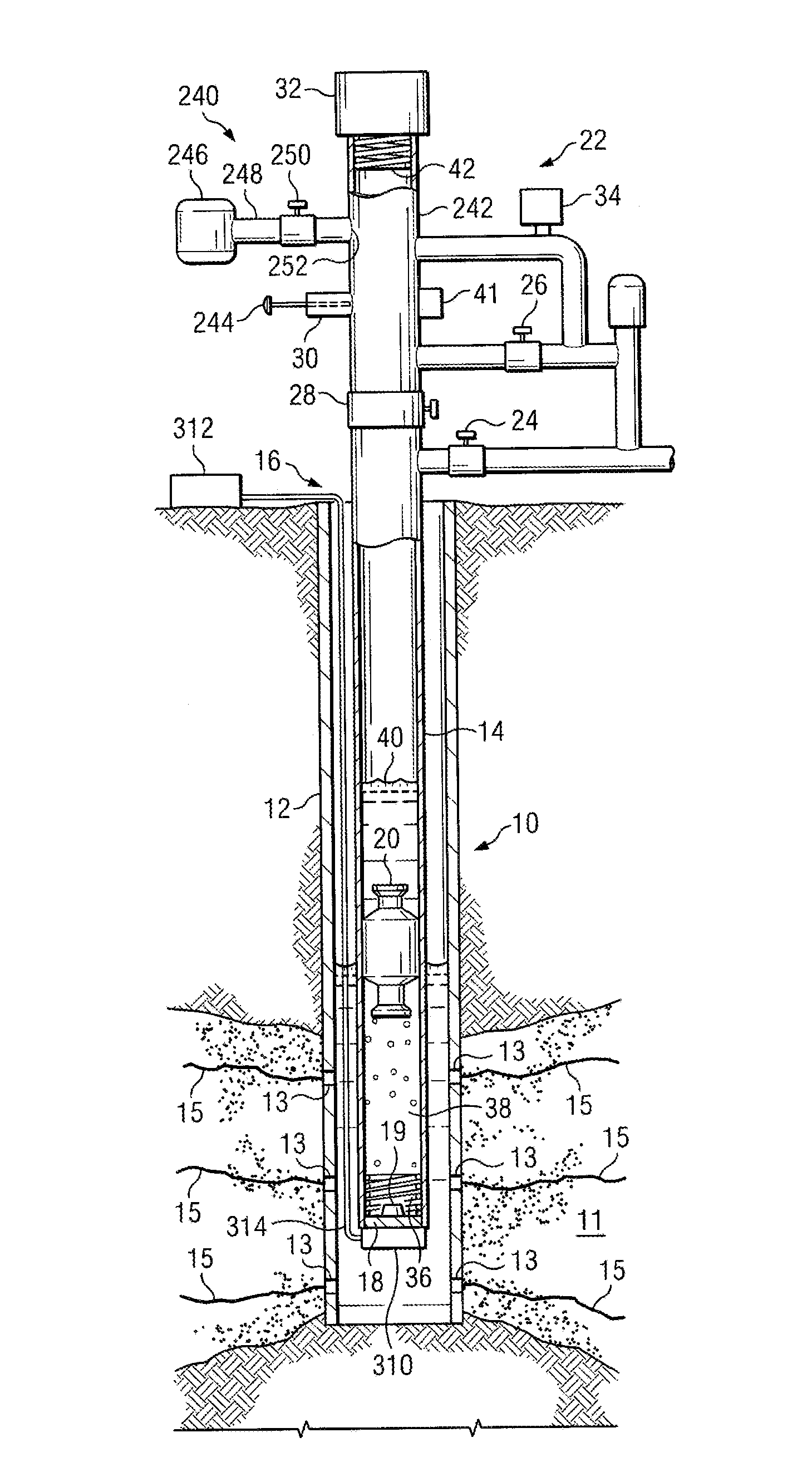
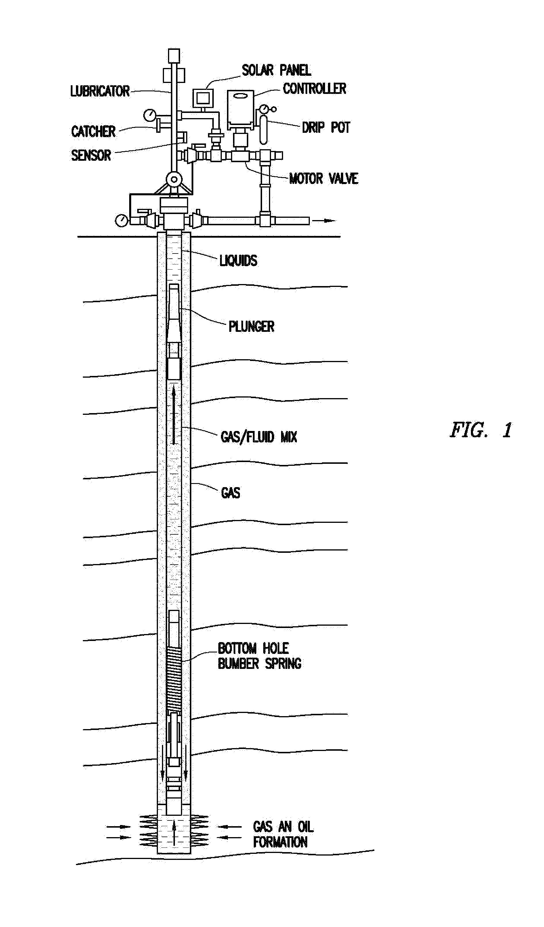
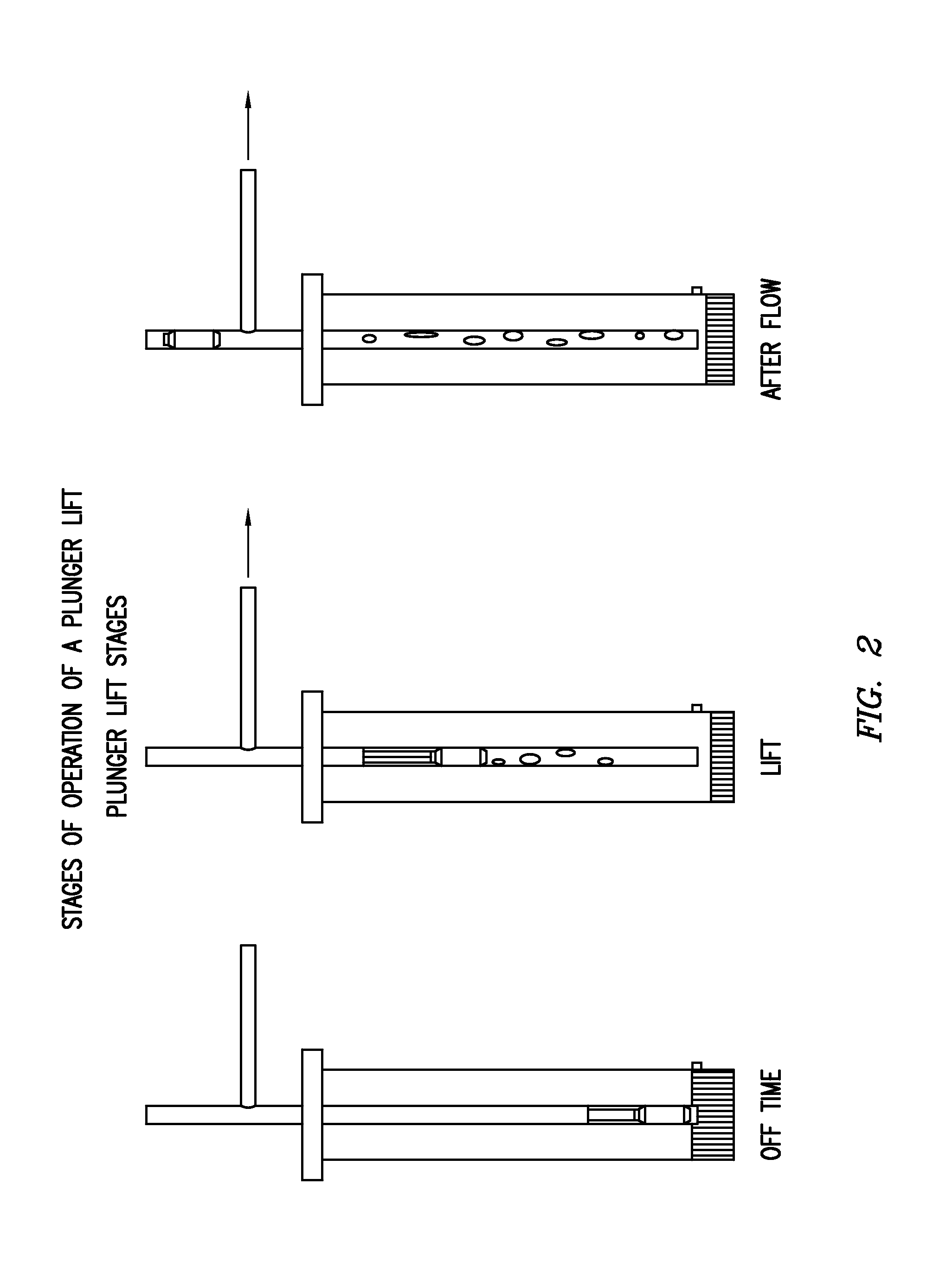
[0099]The disclosure provides novel control logic used to control a plunger lift system to maximize hydrocarbon recovery from a well. The invention comprises any of the following embodiments in any combination thereof:[0100]An improved method of optimizing a ON and OFF cycle of a plunger lift system for a well, the plunger lift system having a cased well, a plunger in the cased well moveable from a stop at the bottom of the cased well to a top of the cased well, a control valve in functional connection with the cased well, a plunger arrival sensor capable of measuring a plunger arrival velocity, a flow valve sensor capable of measuring time flow valve is open or closed, a controller in operational connection with the control valve and functional connection with the sensors for receiving signals from the sensors, wherein the improvement comprises said controller optimizing for Minimum-OFF time for said plunger, or optimizing for Minimum-ON time for said plunger, or both, based on cur...


PUM


Abstract

A logic used to auto-adjust plunger lift system parameters to optimize oil and gas well production with minimal human interaction is described. The auto-adjustments place and maintain the well in an optimized state wherein the well has either a Minimum-OFF time (e.g., length of time just long enough for the plunger to reach the bottom of the well), or Minimum-ON time (e.g., flowing just long enough for the plunger to reach the surface) cycle.

Description

CROSS-REFERENCE TO RELATED APPLICATIONS[0001]This application is a non-provisional application which claims benefit under 35 USC §119(e) to U.S. Provisional Application Ser. No. 61 / 907,227 filed Nov. 21, 2013, entitled “PLUNGER LIFT OPTIMIZATION,” which is incorporated herein in its entirety.FIELD OF THE DISCLOSURE[0002]The disclosure generally relates to optimizing oil production by employing logic steps in a plunger lift controller to adjust cycle parameters in such a way so as to minimize bottom hole pressure and maximize production (i.e. optimize the plunger lift cycle).BACKGROUND OF THE DISCLOSURE[0003]As natural gas is produced from gas wells, the pressure in the formation will decrease, resulting in a reduction in gas flow rate and associated gas velocity. Before the natural drive pressure is reduced, the flow rate and velocity of produced gas may be sufficient to remove the liquids from the well with the gas. However, at some point the flow rate of gas will be insufficient t...

Claims


Application Information

Patent Timeline
Patent Type & Authority Applications(United States)
IPC IPC(8): E21B43/12E21B47/06E21B44/00E21B41/00E21B34/08
CPCE21B43/121E21B41/0092E21B47/06E21B44/005E21B34/085F04B47/12E21B2200/22E21B47/12
Inventor BERGMAN, PATRICK W.
Owner CONOCOPHILLIPS CO
Why Eureka
Try Eureka