Process for removing a contaminant from coal tar

a technology of coal tar and contaminant, which is applied in the direction of chemical refining, metal refining, chemical refining, etc., can solve the problem of increasing the cost of petroleum

Inactive Publication Date: 2015-05-21
UOP LLC
View PDF7 Cites 16 Cited by
  • Summary
  • Abstract
  • Description
  • Claims
  • Application Information

AI Technical Summary

Problems solved by technology

However, petroleum is becoming more expensi...

Method used


Image

  • Process for removing a contaminant from coal tar
  • Process for removing a contaminant from coal tar

Examples


Embodiment Construction

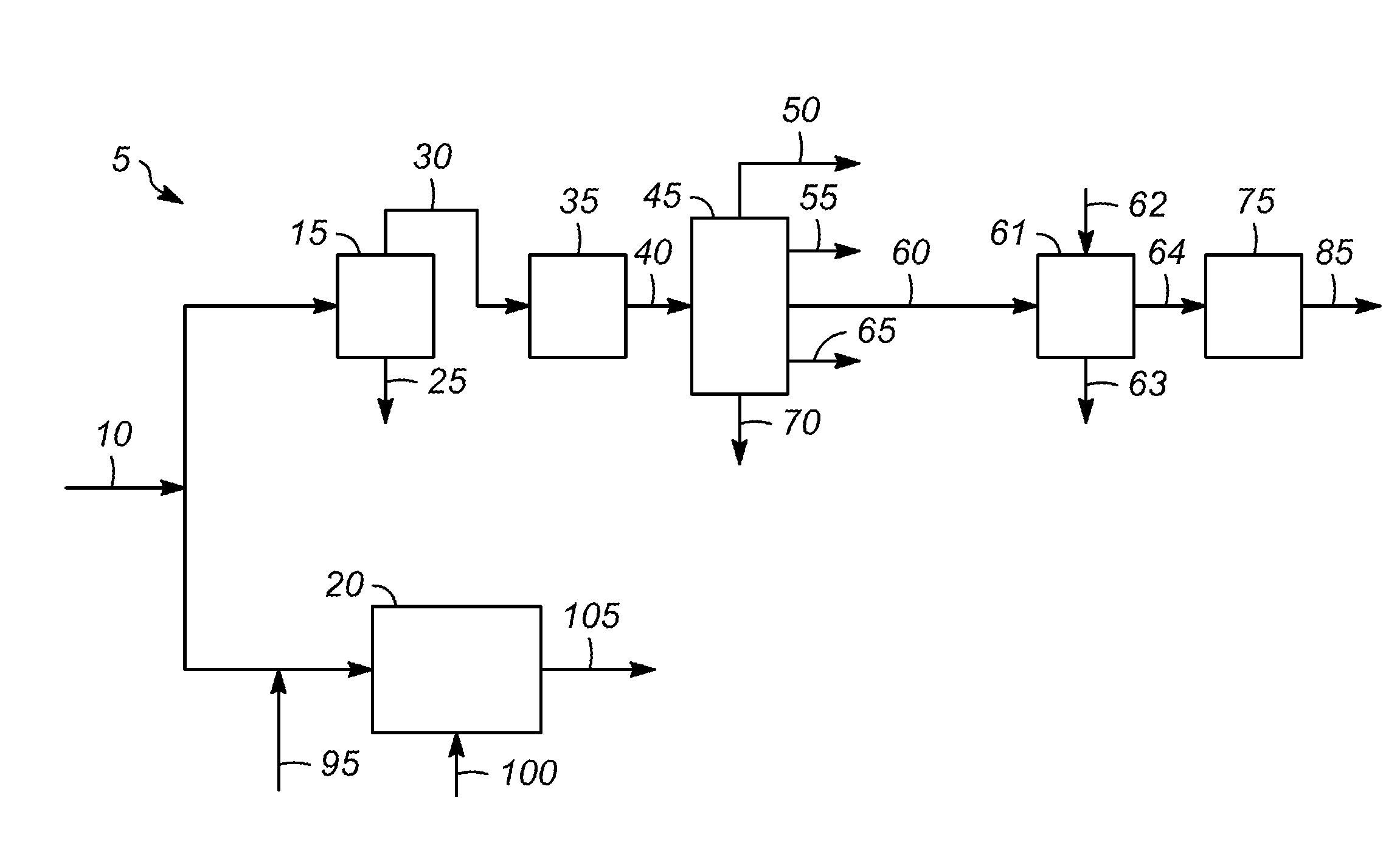
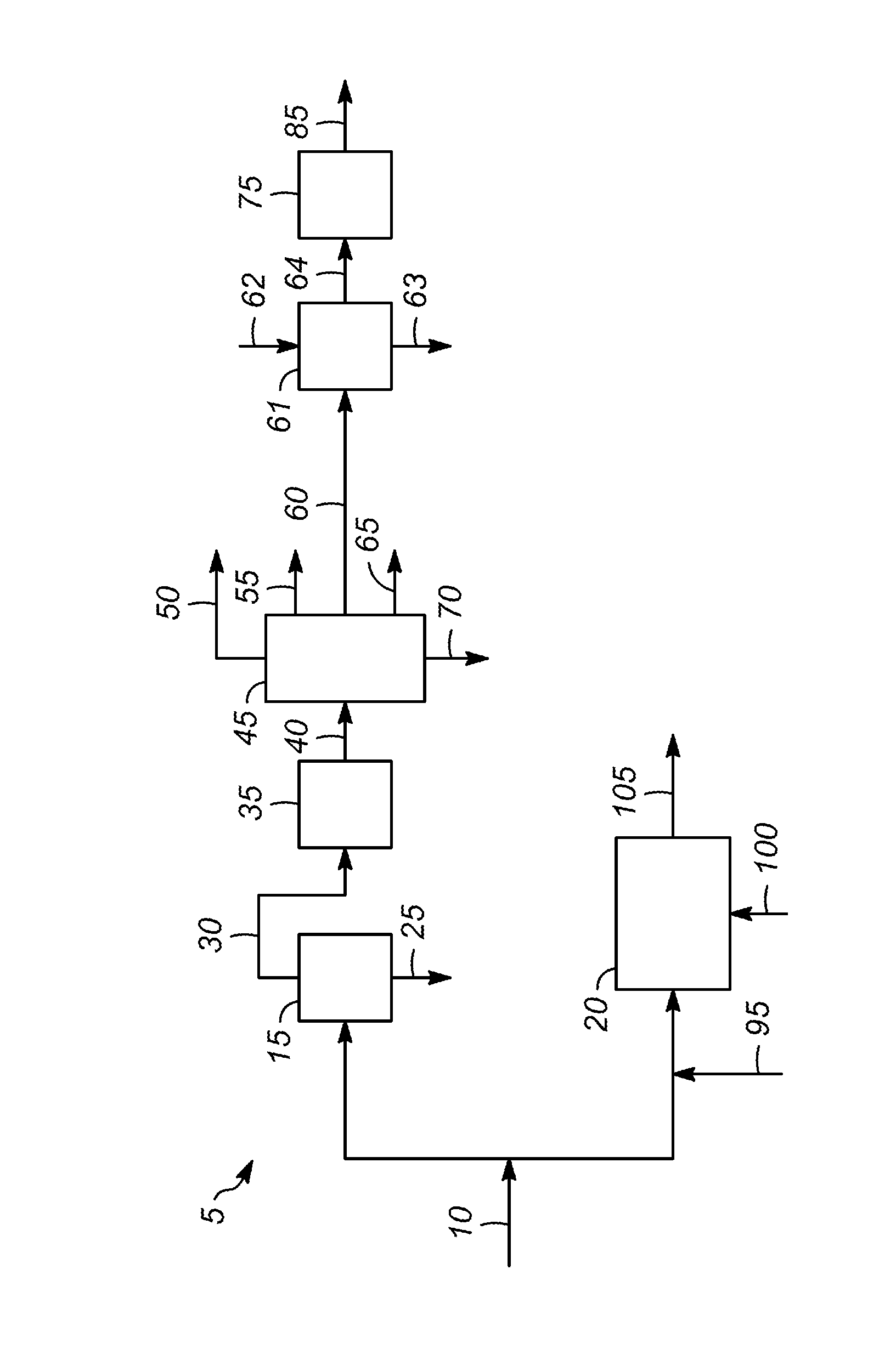
[0010]The FIGURE shows one embodiment of a coal conversion process 5. The coal feed 10 can be sent to the pyrolysis zone 15, the gasification zone 20, or the coal feed 10 can be split into two parts and sent to both.

[0011]In the pyrolysis zone 15, the coal is heated at high temperature, e.g., up to about 2,000° C. (3600° F.), in the absence of oxygen to drive off the volatile components. Coking produces a coke stream 25 and a coal tar stream 30. The coke stream 25 can be used in other processes, such as the manufacture of steel.

[0012]The coal tar stream 30 which comprises the volatile components from the coking process can be sent to an optional contaminant removal zone 35, if desired.

[0013]The contaminant removal zone 35 for removing one or more contaminants from the coal tar stream or another process stream may be located at various positions along the process depending on the impact of the particular contaminant on the product or process and the reason for the contaminant's remov...


PUM


Abstract

A process for removing at least one contaminant from coal tar is described. The process involves extraction with an extraction agent or adsorption with an adsorbent. The extraction agent includes at least one of amphiphilic block copolymers, inclusion complexes of poly(methyl methacrylate) and polycyclic aromatic hydrocarbons, cyclodextrins, functionalized cyclodextrins, and cyclodextrin-functionalized polymers, and the adsorbent includes exfoliated graphite oxide, thermally exfoliated graphite oxide or intercalated graphite compounds.

Description

[0001]This application claims the benefit of Provisional Application Ser. No. 61 / 905,895 filed Nov. 19, 2013, entitled Process for Removing a Contaminant from Coal Tar.BACKGROUND OF THE INVENTION[0002]Many different types of chemicals are produced from the processing of petroleum. However, petroleum is becoming more expensive because of increased demand in recent decades.[0003]Therefore, attempts have been made to provide alternative sources for the starting materials for manufacturing chemicals. Attention is now being focused on producing liquid hydrocarbons from solid carbonaceous materials, such as coal, which is available in large quantities in countries such as the United States and China.[0004]Pyrolysis of coal produces coke and coal tar. The coke-making or “coking” process consists of heating the material in closed vessels in the absence of oxygen to very high temperatures. Coke is a porous but hard residue that is mostly carbon and inorganic ash, which is used in making stee...

Claims


Application Information

Patent Timeline
IPC IPC(8): C10G21/02C10G25/00C10G21/16C10G67/06C10G57/00C10G55/06C10G67/04C10G1/00C10G21/14
CPCC10G21/02C10G1/002C10G25/003C10G21/16C10G67/06C10G57/005C10G55/06C10G67/04C10G21/14C10C1/18C10C1/20C10G25/03C10G57/00
Inventor BEDARD, ROBERT L.GORAWARA, JAYANT K.JAN, DENG-YANGMAHER, GREGORY F.RENDE, DEAN E.
Owner UOP LLC
Why Eureka
Try Eureka