

High surface area catalyst
a catalyst and high surface area technology, applied in the field of catalysts, can solve the problems of reduced efficiency, reduced catalytic efficiency, and large cost of pgm catalysts, and achieve the effects of reducing the effects of catalytic aging, reducing the cost of pgm, and enhancing catalytic efficiency
Inactive Publication Date: 2015-05-21
SDC MATERIALS
View PDF5 Cites 40 Cited by
- Summary
- Abstract
- Description
- Claims
- Application Information
AI Technical Summary
Benefits of technology
The patent aims to develop a material that can improve catalytic efficiency with minimal use of PGM (precious metals) and reduce the effects of catalytic aging.
Problems solved by technology
However, commercially available solid-state catalysts have been unable to fully optimize catalyst surface area.
These PGM catalysts are a considerable portion of the cost of catalytic converters.
Commercially available catalytic converters also display a phenomenon known as “aging,” in which they become less effective over time due, in part, to an agglomeration of the PGM catalyst, resulting in a decreased surface area.
Method used
View moreImage
Smart ImageViewing Examples

Examples
embodiment 1
[0128]A catalytic material comprising: a porous carrier; and a plurality of composite nanoparticles embedded within the porous carrier, wherein each composite nanoparticle comprises a support nanoparticle and a catalytic nanoparticle.
embodiment 2
[0129]The catalytic material of embodiment 1, wherein the catalytic material is a micron-size particle.
embodiment 3
[0130]The catalytic material of embodiment 1 or 2, wherein the catalytic nanoparticle comprises at least one platinum group metal.
Login to View More PUM
 Abstract
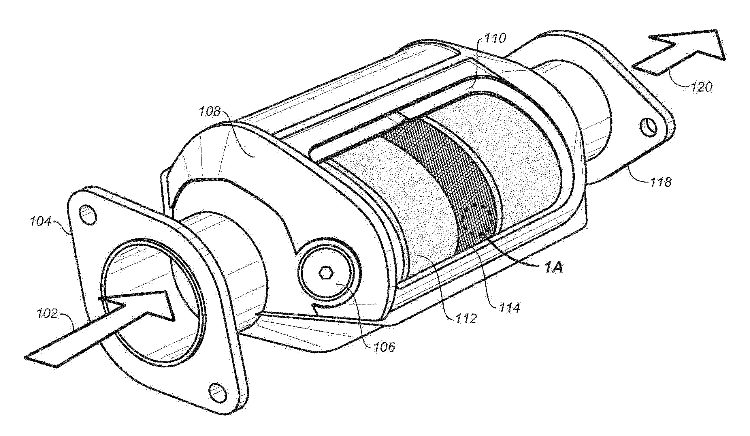
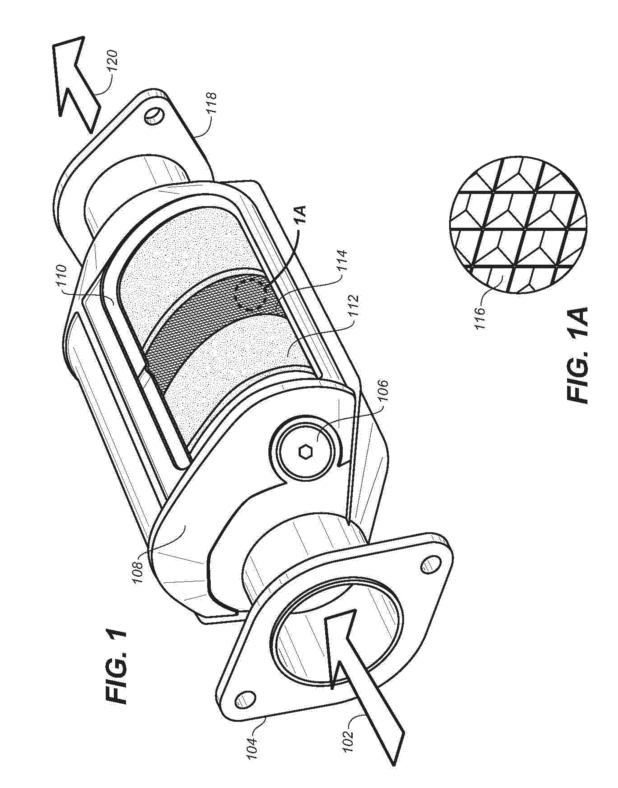
The present invention relates to the field of catalysts, and more specifically to nanoparticle catalysts. Materials with high porosity which contain nanoparticles can be created by various methods, such as sol-gel synthesis. The invention provides catalytic materials with very high catalytically active surface area, and methods of making and using the same. Applications include, but are not limited to, catalytic converters for treatment of automotive engine exhaust.
Description
CROSS-REFERENCE TO RELATED APPLICATIONS[0001]This application claims priority benefit of U.S. Provisional Patent Application No. 61 / 881,337, filed Sep. 23, 2013, of U.S. Provisional Patent Application No. 61 / 984,654, filed Apr. 25, 2014, of U.S. Provisional Patent Application No. 62 / 030,550, filed Jul. 29, 2014, of U.S. Provisional Patent Application No. 62 / 030,555, filed Jul. 29, 2014, and of U.S. Provisional Patent Application No. 62 / 030,557, filed Jul. 29, 2014. The entire contents of those applications are hereby incorporated by reference herein.FIELD OF THE INVENTION[0002]The present invention relates to the field of catalysts, and more specifically to nanoparticle catalysts.BACKGROUND OF THE INVENTION[0003]In solid-state catalysts, efficiency of the catalyst is based, in part, on the amount of catalyst surface area exposed to a target substrate. Smaller and porous particles can generate greater surface area for the amount of catalytic material used. However, commercially avail...
Claims
Login to View More Application Information
Patent Timeline
 Patent Type & AuthorityApplications(United States)
IPC IPC(8): B01J35/02B01J21/04B01J37/02B01J21/08B01J21/18B01J23/44B01J31/06B01J35/00
CPCB01J35/026B01J23/44B01J21/04B01J37/0213B01J21/08B01J21/18B01J37/0221B01J31/068B01D53/94B01D2255/2061B01D2255/2063B01D2255/2065B01D2255/2092B01D2255/30B01D2255/407B01D2255/9202Y10T428/249986B01J37/0018B01J35/393B01J35/23B01J35/643B01J35/651B01J35/615B01J23/40B01J23/56B01J35/50
InventorBIBERGER, MAXIMILIAN A.KEARL, BRYANTQI, XIWANGYIN, QINGHUALEAMON, DAVID
OwnerSDC MATERIALS