
Deformation measurement sensor for measuring pressure and shearing force and structure therefor

Active Publication Date: 2015-05-28
KOREA ELECTRONICS TECH INST
View PDF0 Cites 1 Cited by
  • Summary
  • Abstract
  • Description
  • Claims
  • Application Information

AI Technical Summary

Benefits of technology

This patent is about a new sensor that can measure how much a material is deformed when it is subjected to pressure or shearing force. The sensor has a very precise way to measure this deformation, and it is very small compared to the size of the sensor. This allows for the creation of very thin and compact sensors. Additionally, the sensor is designed in a way that helps reduce interference between different parts, which means it can measure the deformation of a certain part of the material without affecting other parts.

Problems solved by technology

However, the pressure sensor can only measure the deformation rate caused by pressure applied in a perpendicular direction on the structure, and thus it is difficult to measure a deformation rate caused by pressure applied in a parallel direction on the structure.
Further, since it is required to have a separate deforming structure to measure the deformation rate caused by a shearing force, there is a problem in that overall size of the sensor increases.

Method used


Image

  • Deformation measurement sensor for measuring pressure and shearing force and structure therefor
  • Deformation measurement sensor for measuring pressure and shearing force and structure therefor
  • Deformation measurement sensor for measuring pressure and shearing force and structure therefor

Examples


first embodiment

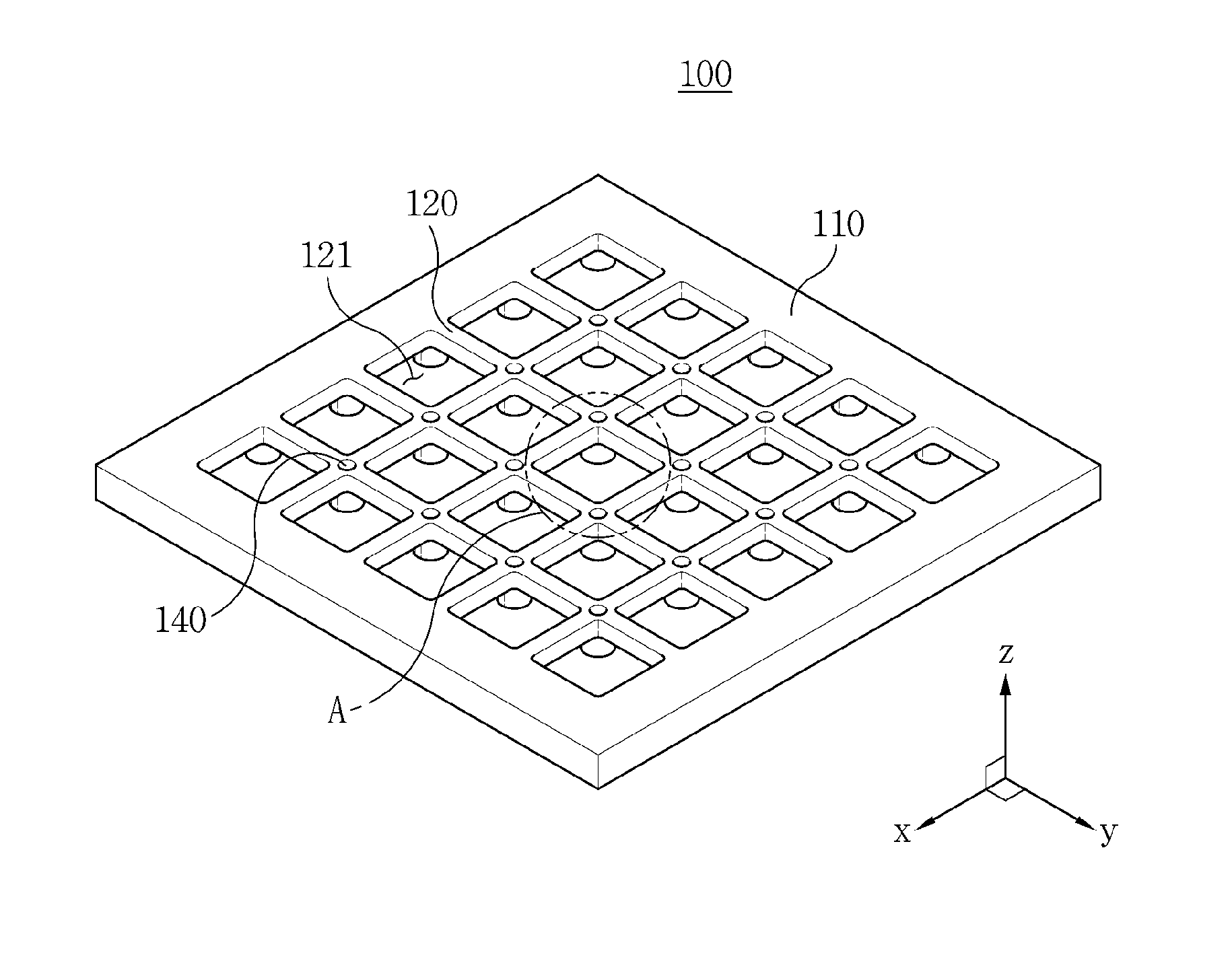
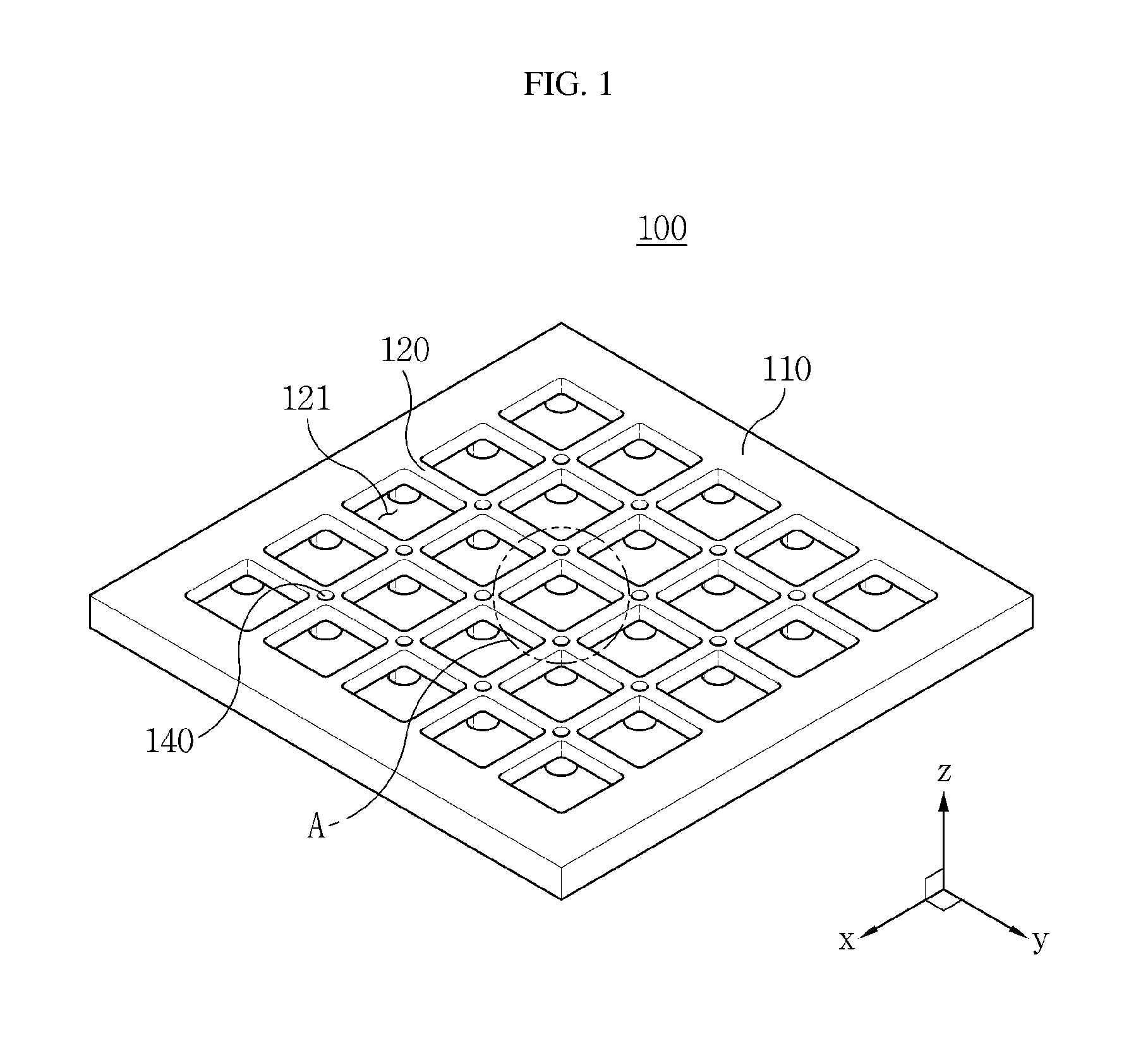
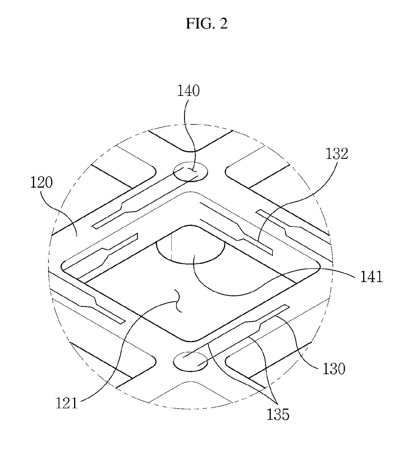
[0031]Referring FIGS. 1 to 3, the sensor for measuring deformation 100 of the first embodiment includes a frame 110, a plurality of beams 120, strain gauges 130, 131, and 132 and holes for wirings 140.

[0032]The frame 110 is hollow at the center, surrounds the plurality of beams 120, and has a thickness greater than the plurality of beams 120.

[0033]The plurality of beams 120 are formed in a lattice shape with spaces 121 formed through the frame 110 as a structure being deformed by pressure or shearing force. Since the plurality of beams 120 have smaller thicknesses than the frame 110, the plurality of beams 120 can be easily deformed by pressure or shearing force.

[0034]Each of the strain gauges 130, 131, and 132 is respectively attached onto a top or bottom of each of the beams 120 and one or more of both side surfaces of each beam 120, and measures the deformation rate.

[0035]The strain gauge 130 attached on the top of the beam 120 and the strain gauge 131 attached on the bottom of t...

second embodiment

[0061]In the sensor for measuring deformation 200 the signal process module 150 is disposed on the same substrate as the sensor for measuring deformation 200, and the signal process module 150 receives the deformation rate measurement signals measured by the strain gauges 130 via conductive circuits of the substrate. The sensor for measuring deformation 200 configured to be disposed on a single substrate makes it easy to manufacture the sensor for measuring deformation 200 with the signal process module 150.

[0062]Although the sensor for measuring deformation 200 with the signal process module 150 is implemented on a single substrate 160 in the second embodiment, the signal process module 150 may be disposed on a separate substrate according to embodiment, and all of the embodiments are contemplated as being within the scope of the invention.

[0063]Referring FIG. 5, the signal process module 150 includes an amplifier 151, a signal processor 152 and an offset adjustor 153.

[0064]The am...


PUM


Abstract

A deformation measurement sensor for measuring pressures and shearing forces according to the present invention includes: a plurality of beams shaped like a lattice; a strain gauge attached to each of the plurality of beams for measuring a deformation rate; a frame connected to the end of the lattice shape for surrounding the plurality of beams; and holes for arranging lines and formed in the intersections of the plurality of beams, whereby it is possible to precisely measure the deformation rate depending on the pressures or shearing forces exerted to a plurality of areas.

Description

TECHNICAL FIELD[0001]The present invention relates to a deformation measurement technique, and more particularly, to a deformation measurement sensor of measuring pressure and shearing force, which precisely measures deformation caused by pressure and shearing force at a plurality of points, and a structure thereof.BACKGROUND ART [0002]As pressure sensors are elements for measuring pressure in a certain system, the pressure sensors are widely used in various applications including an industrial instrumentation, an automatic control, a medical device, motor engineering apparatuses, an environment control, and an electrical apparatus applications, etc. The measurement principle of the pressure sensors is based on measuring electrical variations due to displacement or deformation, etc, and various types of the sensors are implemented.[0003]Types of the pressure sensors include a mechanical pressure sensor using the Bourdon tube or bellows, a pressure-resistive electronic pressure senso...

Claims


Application Information

Patent Timeline
IPC IPC(8): G01B7/16G01L1/22
CPCG01B7/16G01L1/22G01L1/18G01L1/205G01L5/0057G01L5/162
Inventor HWANG, JUNGHOONKIM, YOUNGOUK
Owner KOREA ELECTRONICS TECH INST
Learn More