High-stability light source system and method

a light source and high-stability technology, applied in the field of light source systems, can solve the problems of reducing the wall-plug efficiency of a light source, affecting the efficiency of the light source, and compromising the performance of the conventional source to achieve acceptable peak wavelength,

Inactive Publication Date: 2015-05-28
USL TECH
View PDF3 Cites 14 Cited by
  • Summary
  • Abstract
  • Description
  • Claims
  • Application Information

AI Technical Summary

Benefits of technology

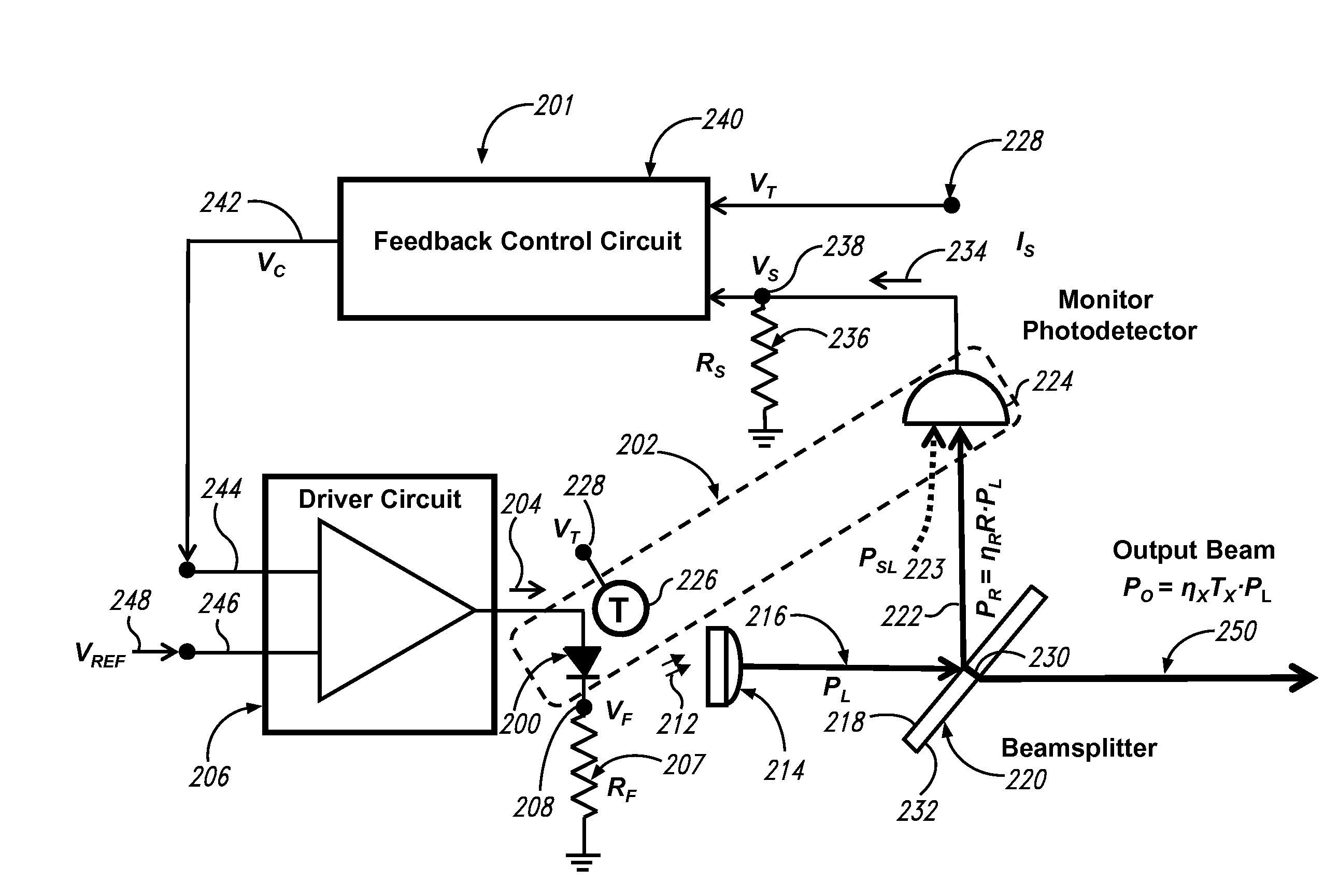
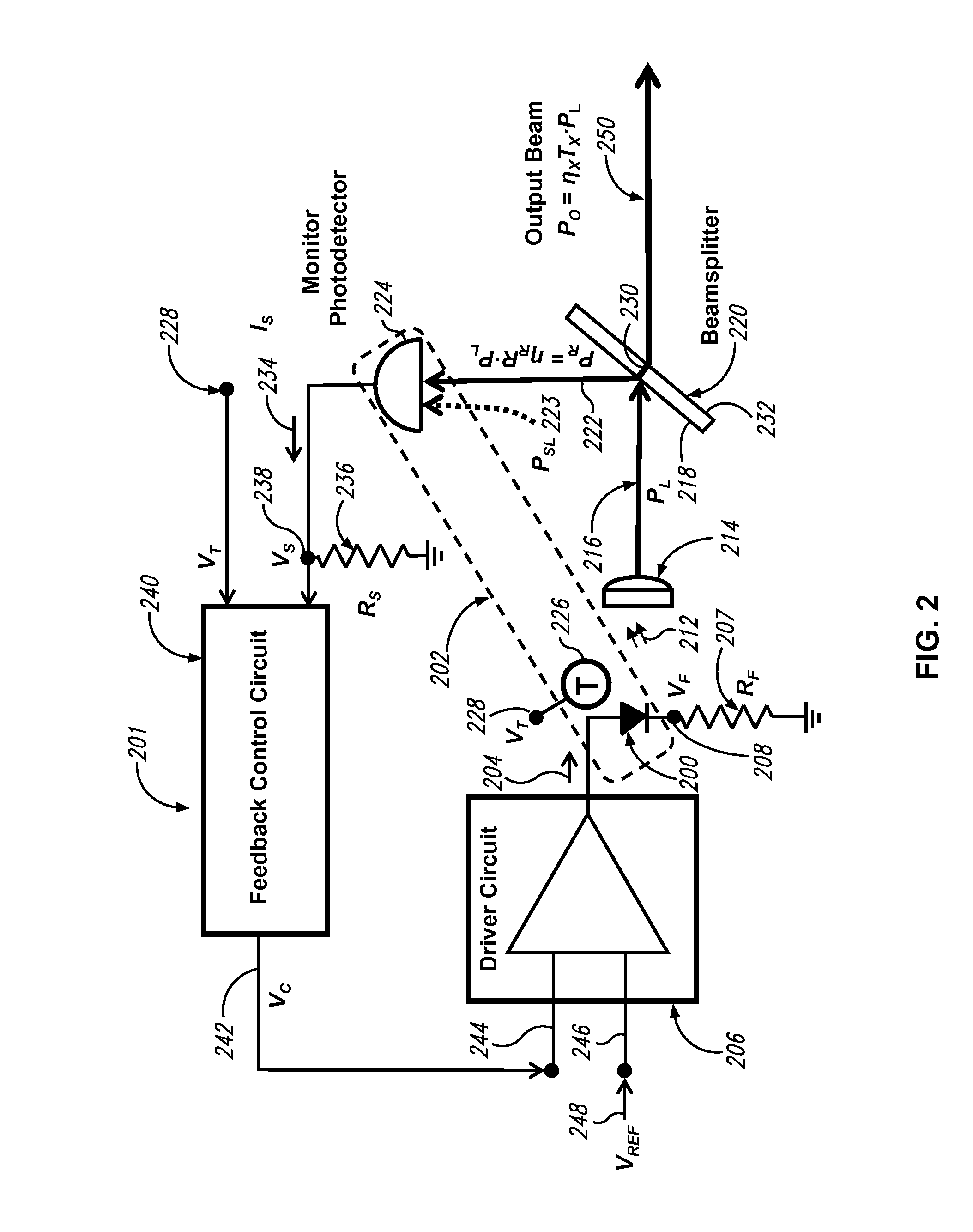
[0012]The present disclosure provides a method and system of stabilizing light output from a light source.

Problems solved by technology

Instead, conventional sources compromise performance to achieve acceptable peak wavelength, bandwidth, power, stability, electrical power consumption, size, and cost.
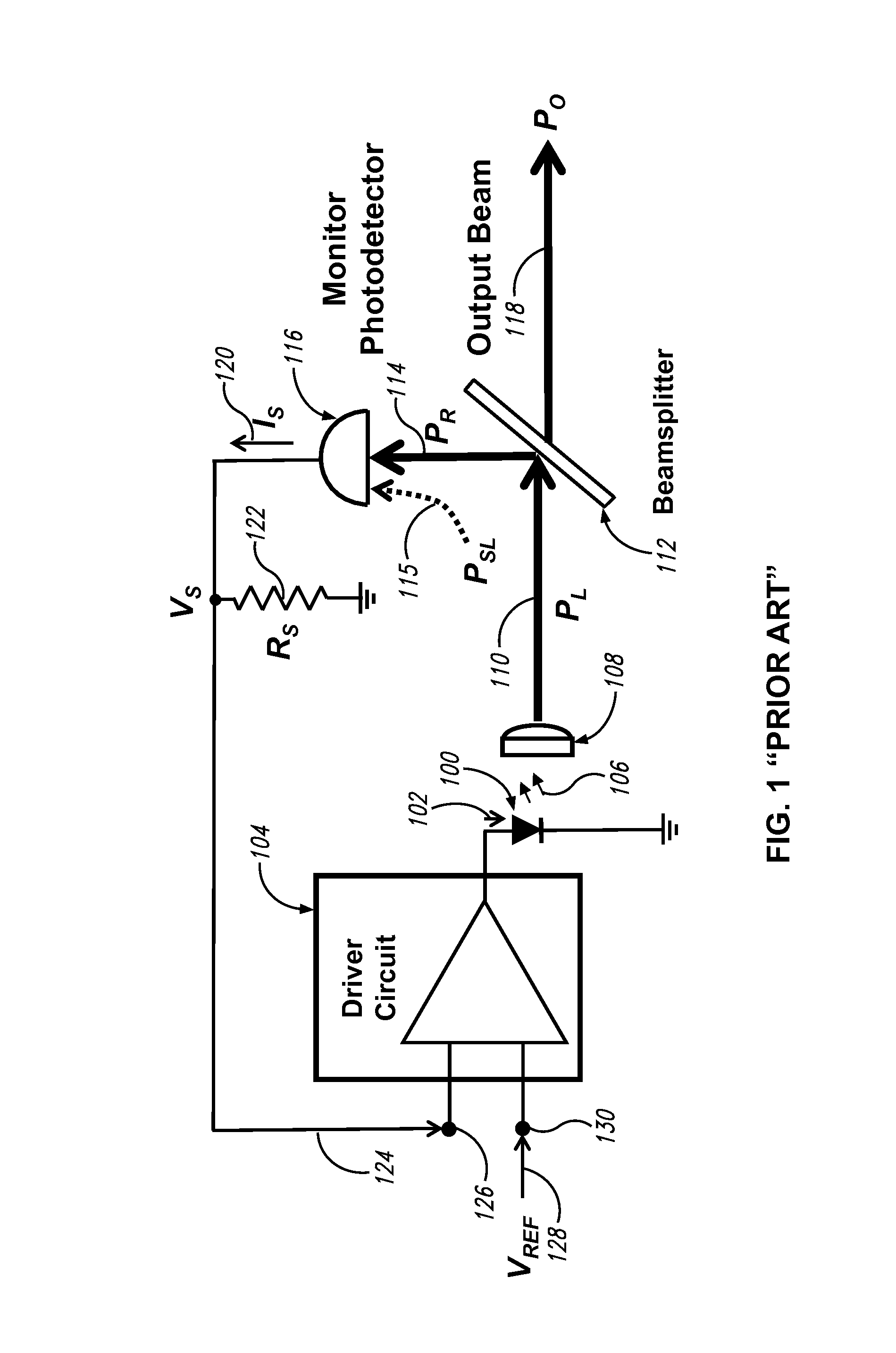
An open loop controller relies on inputs other than the output light power itself and cannot respond to deterioration of a semiconductor emitter during its life.
Light-source systems having open-loop controllers will therefore drift unpredictably as the light emitter power declines with age, and the host sensing device will require periodic calibration.
The use of a TEC, however, substantially reduces the wall-plug efficiency of a light source.
A first manufacturing challenge of the optical method is that the coating reflectance can change as much as 1.8% (18,000 ppm) for a one-degree change of angle of incidence.
A second challenge is the spectral tolerance of coating reflectance, which can vary by several percentage points within a batch of beamsplitter coatings.
This tolerance substantially reduces production yields and necessitates costly laser-alignment equipment.
These requirements preclude the use of thermoelectric coolers (TECs) to stabilize wavelength and power because TECs consume as much as a watt of electrical power.
In summary, a state of the art light source with peak wavelength variations less than 20 nm over 50° C. and light source power that can be stabilized to 25 ppm per ° C. exists but only at a high manufacturing cost that substantially limits the market.

Method used


Image

  • High-stability light source system and method
  • High-stability light source system and method
  • High-stability light source system and method

Examples


Embodiment Construction

[0035]In the following description, certain specific details are set forth in order to provide a thorough understanding of various disclosed implementations. However, one skilled in the relevant art will recognize that implementations may be practiced without one or more of these specific details, or with other methods, components, materials, etc. In other instances, well-known structures or components or both associated with semiconductor light sources, including but not limited to light emitting diodes, lenses, glass plates, and mirrors, have not been shown or described in order to avoid unnecessarily obscuring descriptions of the implementations.

[0036]Unless the context requires otherwise, throughout the specification and claims which follow, the word “comprise” and variations thereof, such as, “comprises” and “comprising” are to be construed in an open, inclusive sense that is as “including, but not limited to.”

[0037]Reference throughout this specification to “one implementation...


PUM


Abstract

A light source system that generates stable optical power over time and temperature in which a feedback control circuit is operative to receive a temperature signal and a sample signal and in response thereto generate a control signal to a driver circuit to maintain a power level of the light output substantially constant over an operative temperature range defined by Tmin and Tmax.

Description

BACKGROUND[0001]1. Technical Field[0002]The present disclosure pertains to the generation of ultraviolet (UV), visible (VIS), and near-infrared (NIR) light and, more particularly, to a light source system that generates stable optical power over time and temperature.[0003]2. Description of the Related Art[0004]Constant-power light sources are desired for industrial, medical, and military sensing and measurement applications where the light power ideally remains unchanged for all operating temperatures. An example of industrial sensing wherein accuracy depends on constant light power is the determination of water clarity by optical means. In this application, a water sample is illuminated with a light source and the intensity of light scattered from the illuminated sample is measured with a photodetector. Clear water will scatter relatively little light and turbid water will scatter relatively more of it. An accurate measurement is obtained when the change in scattered light intensit...

Claims


Application Information

Patent Timeline
Patent Type & Authority Applications(United States)
IPC IPC(8): H05B37/02H01S5/0683H05B33/08H05B44/00
CPCH05B37/0227H01S5/0683H05B33/0851H01S5/06804A62D3/00G01J3/10H05B45/18
Inventor DOWNING, JOHN P.
Owner USL TECH
Why Eureka
Try Eureka