Antenna for hearing device, ear tip and hearing device provided with such an antenna

a technology for hearing devices and antennas, which is applied in the field of hearing devices, can solve the problems of significant design difficulties, occupying significant space in the hearing device, and modern hearing devices are extremely small, and achieves the effects of improving the individual's acoustical perception, avoiding acoustic signals, and simple rotational construction

Active Publication Date: 2015-05-28
SONOVA AG
View PDF3 Cites 21 Cited by
  • Summary
  • Abstract
  • Description
  • Claims
  • Application Information

AI Technical Summary

Benefits of technology

[0009]Specifically, this is achieved by an antenna module for a hearing device comprising a hollow core and a winding provided around said core that can be connected with a hearing device. The core can be cylindrical, conical, tapered, funnel-shaped, trumpet shaped, of oval longitudinal cross-section, or any other convenient shape. The core comprises an axial passageway, which can be cylindrical, trumpet-shaped, horn-shaped, conical, tapered, funnel-shaped, or any other convenient shape, and the antenna module is adapted to be at least partially, optionally completely, containable within the ear canal of a user. By configuring the antenna module to be at least partially or completely containable within the ear canal and with the above-mentioned hollow axial passageway gives at least one of the following advantages:1. In use, when incorporated into a hearing device, the antenna can be physically separated from interference-causing components in the hearing device by situating the antenna deep in the ear canal away from the electronics of the hearing device, thus reducing and / or completely eliminating the necessity for shielding and / or compensation coils. This simplifies the construction of the hearing device, and enables the hearing device to be made smaller than at present, and thereby produces cost savings in manufacture.2. The size of a hearing device with wireless function can be reduced, due to the reduction / elimination of shielding and / or compensation, and as a result of moving the antenna away from the circuitry and / or out of the shell of the hearing device and into normally unused space in the ear canal.3. Particularly in the case of CIC's (although it equally applies to BTE and ITE-types) with wireless link, the ability to position the antenna modules at least partially in the ear canal improves the wireless link between the two hearing devices by permitting positioning of the antennas closer together than is possible with current solutions, to the tune of 30-40 mm when the antenna module is situated deeply inserted into the ear canal. This optimises the antenna positioning for this application. In addition, it should be noted that with current wireless technologies working at high frequencies, e.g. of the order of 2.4 GHz, a hole in the core of the antenna has no negative effect on the antenna's gain.4. Due to the axial passageway in the core, sound can travel through the core rather than having to be guided around it by a tube as it would in the case of a conventional solid cylindrical core if arranged to be disposed at least partially within the ear canal. This enables greater design freedom of acoustical tubing. Indeed, the core itself may form part of the acoustical tubing, i.e. the sound-guiding pathway from the receiver to the user's ear.
[0021]In an embodiment, the hearing device may further comprise a wax guard, for protecting the interior of the hearing device from cerumen emanating from the wearer's ear. The present arrangement with a hollow antenna enables a simple, rotationally-symmetrical construction of the wax guard in comparison with a conventional, solid-core antenna arranged next to a tube, which requires a complicated wax guard shape to fit around the solid antenna.

Problems solved by technology

Modern hearing devices have become extremely small, particularly in the case of ITE, CRT and CIC-type devices, and often incorporate a plurality of functionalities.
This presents the disadvantages of taking up significant amounts of space in the hearing device and presenting significant design difficulties.
In addition, the coil is often subject to parasitic electromagnetic fields emanating from electrical components in the hearing device, particularly from the receiver.
As a result, shielding and / or compensation coils are required, which are bulky and take up a significant amount of space in the hearing device, to eliminate the negative effects of these parasitic electromagnetic fields.
While this saves space in the hearing device and allows increasing of the diameter of the antenna coil, this arrangement is also subject to undesired electromagnetic interference from the electromagnetic components, particularly those contained within the volume delimited by the antenna coils.
Furthermore, this arrangement prohibits the use of a magnetically permeable core, limiting the gain of the antenna.

Method used


Image

  • Antenna for hearing device, ear tip and hearing device provided with such an antenna
  • Antenna for hearing device, ear tip and hearing device provided with such an antenna
  • Antenna for hearing device, ear tip and hearing device provided with such an antenna

Examples


first embodiment

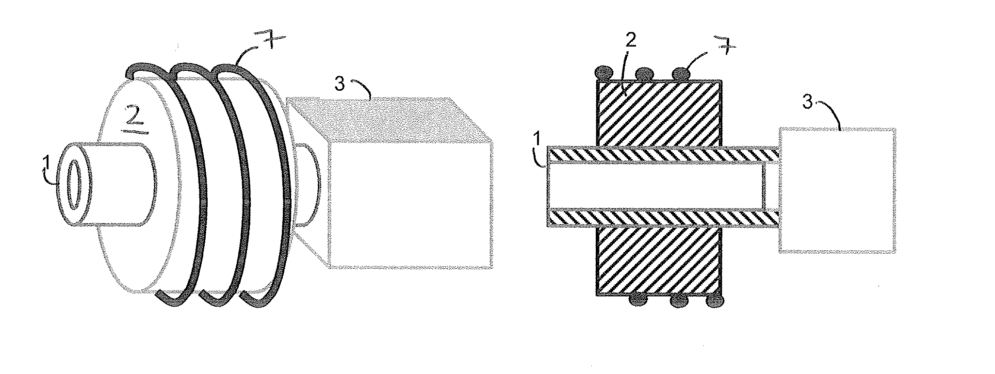
[0031]FIG. 1 illustrates an antenna module according to the invention. This antenna module comprises a core 2 formed substantially as a hollow cylinder, i.e. a cylinder with an axial passageway. Although a hollow cylindrical core is illustrated in the figures with a cylindrical axial passageway, many other shapes are foreseen as falling within the scope of the current invention. The core can be cylindrical, conical, tapered, funnel-shaped, trumpet shaped, of oval longitudinal cross-section, or any other convenient shape. The axial passageway can be cylindrical, trumpet-shaped, horn-shaped, conical, tapered, -funnel-shaped, or any other convenient shape. The shape of the passageway can thereby be conformed so as to tailor the acoustic properties of the overall sound passageway. The core may be constructed of a magnetically permeable material, such as ferrite, or may be constructed of a non-magnetic material such as plastic. Around the core 2 is an electrically-conductive winding 7 in...

second embodiment

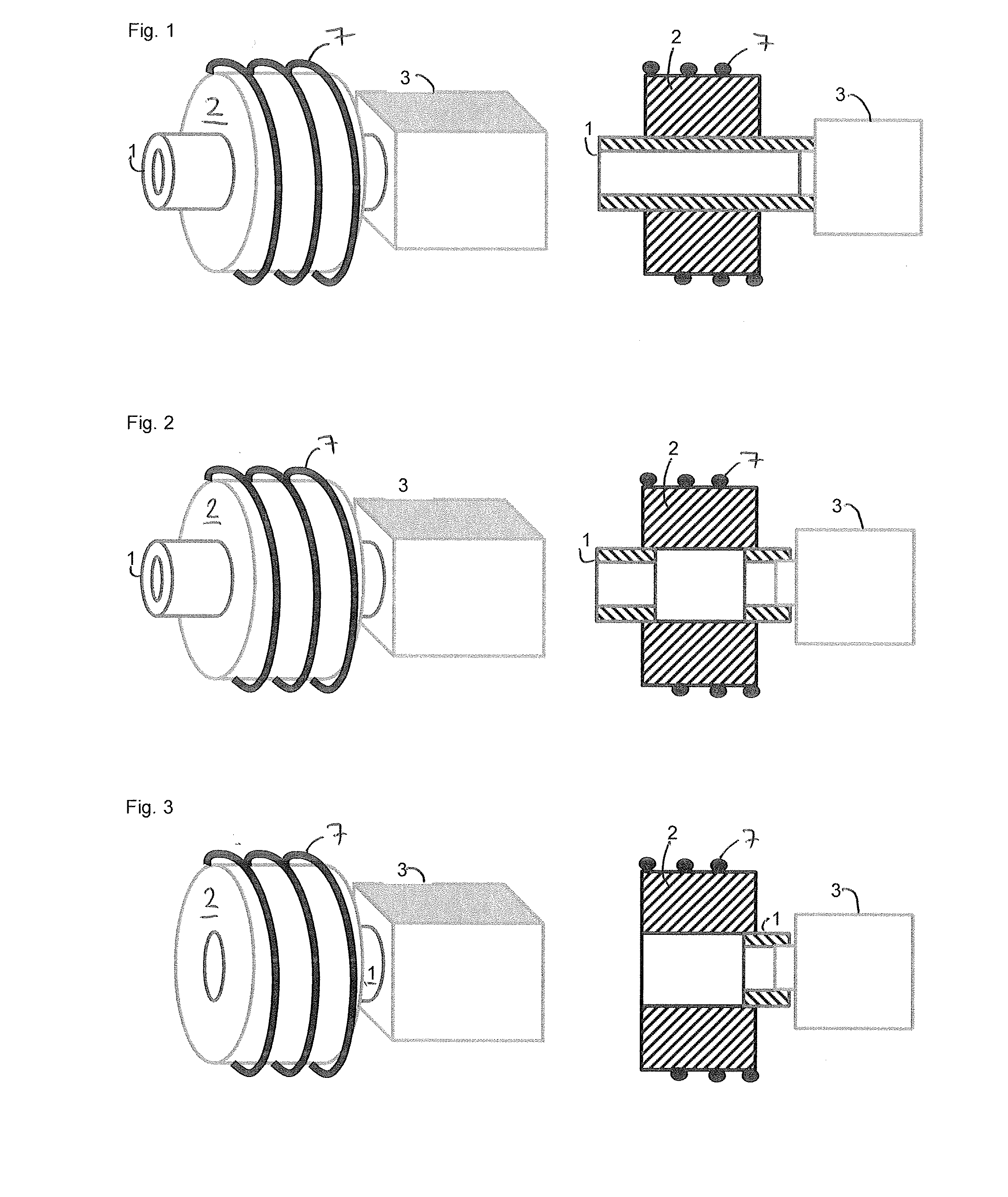
[0032]FIG. 2 illustrates an antenna module according to the invention. The core 2 and the winding 7 are substantially identical to those in FIG. 1, however two pieces of tubing 1 are provided, one in each end of the axial passageway in the core 2. One of these sections of tubing is connected with the acoustic output of the receiver 3, and the other, in use, will transmit the acoustic output to the user. It should be noted that in this embodiment the passageway through the core 2 itself forms part of the acoustic pathway from the receiver 3 to the user.

third embodiment

[0033]FIG. 3 illustrates an antenna module according to the invention, which differs from that of FIG. 2 only in that a single, short piece of tube 1 is used to connect the passageway through the core 2 to the receiver 3. In this embodiment, the majority of the acoustic pathway from the receiver 3 to the user is constituted by the passageway through the core 2.

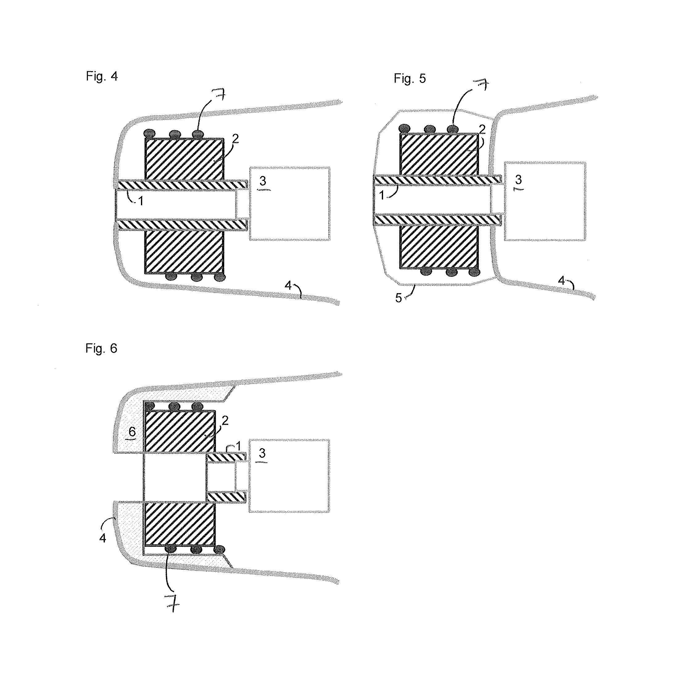
[0034]FIG. 4 illustrates the antenna module according to the first embodiment of the invention integrated into the shell 4 of an ear tip or a hearing device. A shell may be customised to fit a particular wearer or may by a standard shape. Although the antenna module according to the first embodiment is illustrated here, it is evident that any of the other embodiments could be substituted in its place.

[0035]FIG. 5 illustrates the antenna module according to the first embodiment of the invention integrated into an ear tip or a hearing device comprising a shell 4 but situated outside of the custom shell 4. In this case, the anten...


PUM


Abstract

The present invention relates to an antenna module for a hearing device. The antenna module comprises a hollow core provided with an axial passageway and a winding around the core which is connectable with a hearing device. The antenna module is arranged to be at least partially contained within the ear canal of a user. This enables the antenna to be separated from sources of interference, since it can be positioned inside the ear canal away from hearing device electronics, thus reducing requirements for shielding and / or compensation. The invention further relates to an ear tip and a hearing device comprising such an antenna module.

Description

BACKGROUND OF THE INVENTION[0001]1. Field of the Invention[0002]The invention relates to the field of hearing devices, such as hearing aids and active hearing protection devices, and more particularly to an antenna module for hearing devices capable of receiving and / or transmitting electromagnetic signals. Furthermore, the invention relates to an ear tip comprising such an antenna module, and a hearing device comprising the same.[0003]2. Description of the Related Art[0004]Modern hearing devices have become extremely small, particularly in the case of ITE, CRT and CIC-type devices, and often incorporate a plurality of functionalities. For instance, it has become increasingly common for a wireless link to be incorporated in hearing devices, for various purposes such as receiving information, e.g. as electromagnetically encoded sound information from an induction loop; wireless programming of the hearing device; or for establishing a wireless link between two hearing devices, or betwe...

Claims


Application Information

Patent Timeline
Patent Type & Authority Applications(United States)
IPC IPC(8): H04R25/00
CPCH04R25/652H04R2225/021H04R2225/51H04R2225/025H04R2225/023H01Q1/273H01Q7/00H04R25/552H04R25/554H04R25/60H04R25/654H04R2225/49
Inventor VONLANTHEN, ANDIGEHRING, STEPHANLEIST, CHRISTOPHJAKOB, ANDREASPROBST, DANIEL
Owner SONOVA AG
Why Eureka
Try Eureka