Image processing apparatus and method, and ultrasonic diagnostic apparatus

Active Publication Date: 2015-05-28
SONY CORP
View PDF3 Cites 4 Cited by
  • Summary
  • Abstract
  • Description
  • Claims
  • Application Information

AI Technical Summary

Benefits of technology

[0021]With the present disclosure, it is possible to detect a displacement. In par

Problems solved by technology

Accordingly, it is not possible to correctly detect a d

Method used


Image

  • Image processing apparatus and method, and ultrasonic diagnostic apparatus
  • Image processing apparatus and method, and ultrasonic diagnostic apparatus
  • Image processing apparatus and method, and ultrasonic diagnostic apparatus

Examples


first embodiment

[0036]Example of Axes and Movement of Probe

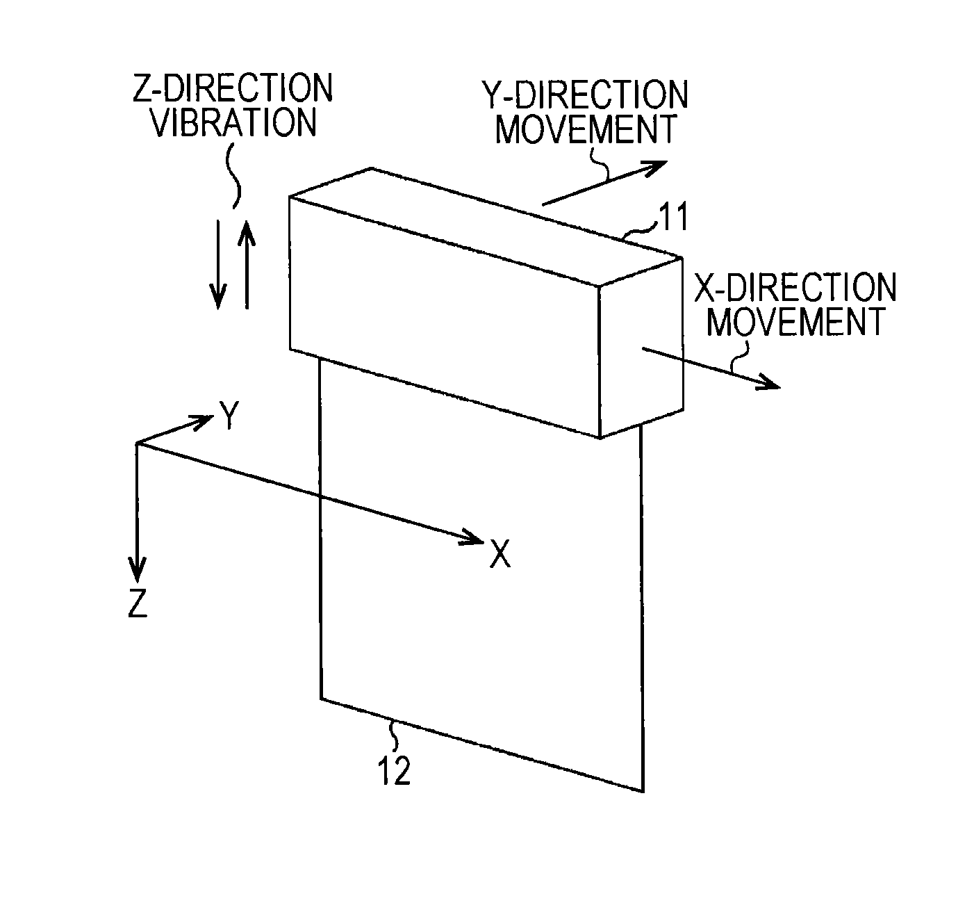
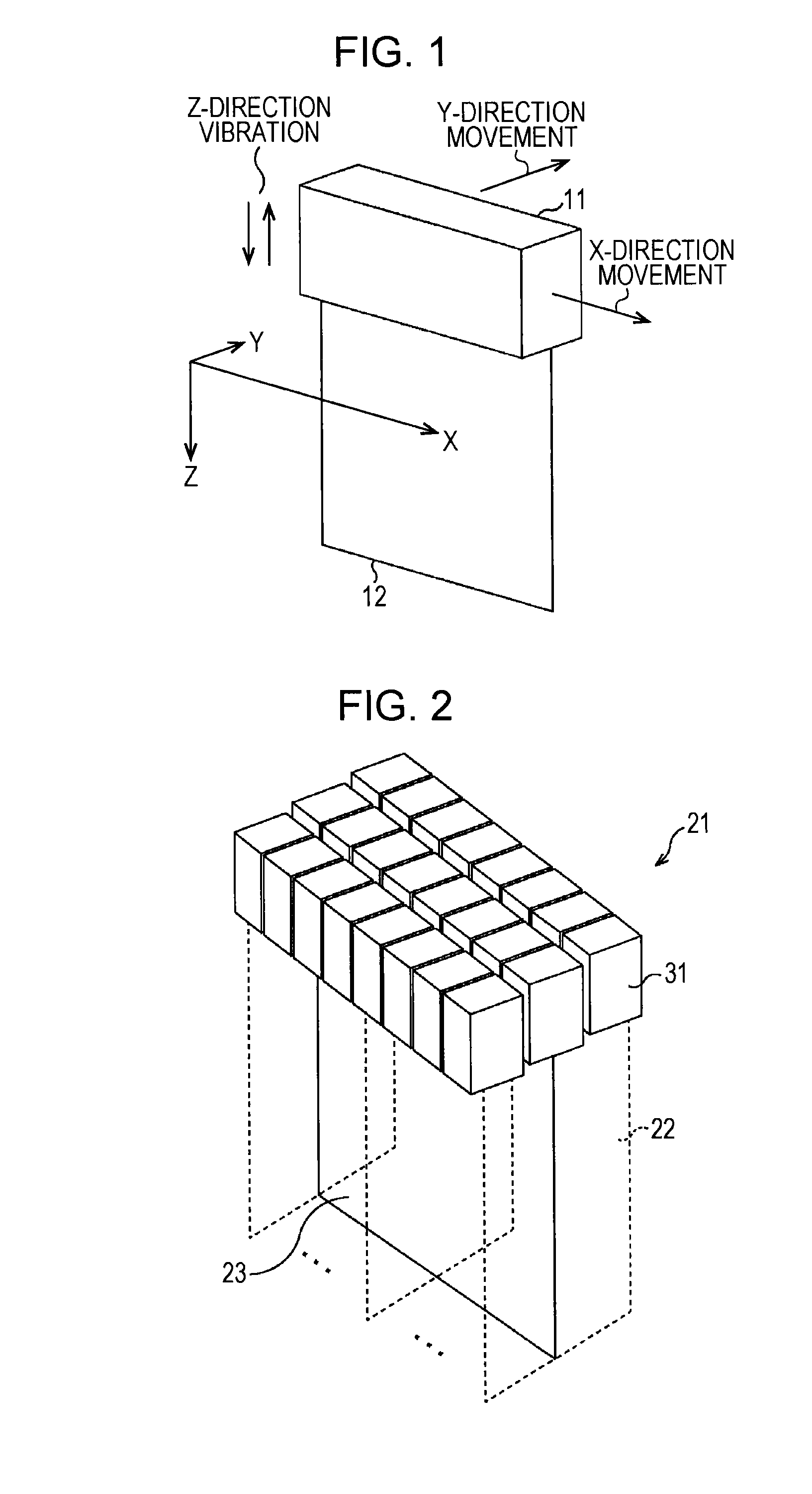
[0037]First, a description will be given of the axes and the movement of a probe with reference to FIG. 1. In this regard, in order to simplify the description, it is assumed that a 1D probe is cuboid-shaped.

[0038]As axes of a probe 11, an X-axis, a Y-axis, and a Z-axis are assigned to a major axis direction, a minor axis direction, and a depth direction, respectively. In the following, a description will be given using XYZ. The probe 11 includes a plurality of piezoelectric elements in an array. The major axis direction is a direction in which a larger number of piezoelectric elements in the array are arranged than that of the minor axis direction, and is a direction in which the overall length of the piezoelectric elements is long. The minor axis direction is a direction in which a smaller number of piezoelectric elements in the array are arranged than that of the major axis direction, and is a direction in which the overall length of the...

second embodiment

[0131]Example of Configuration of Computer

[0132]FIG. 11 is a block diagram illustrating an example of a hardware configuration of a computer that executes the above-described series of processing by programs.

[0133]In the computer, a CPU (Central Processing Unit) 401, a ROM (Read Only Memory) 402, and a RAM (Random Access Memory) 403 are mutually connected through a bus 404.

[0134]An input / output interface 405 is further connected to the bus 404. An input section 406, an output section 407, a storage section 408, a communication section 409, and a drive 410 are connected to the input / output interface 405.

[0135]The input section 406 includes a keyboard, a mouse, a microphone, and so on. The output section 407 includes a display, a speaker, and so on. The storage section 408 includes a hard disk, a nonvolatile memory, and so on. The communication section 409 includes a network interface, and so on. The drive 410 drives a removable recording medium 411, such as a magnetic disk, an optica...


PUM


Abstract

An image processing apparatus includes: when a probe is moved, a shift amount correction section configured to correct an amount of shift from a first frame to a second frame being a frame at different time from the first frame; and a distortion amount calculation section configured to calculate an amount of distortion on the basis of a phase difference detected from the first frame and the second frame having been subjected to shift amount correction by the shift amount correction section.

Description

CROSS REFERENCE TO RELATED APPLICATIONS[0001]This application claims the benefit of Japanese Priority Patent Application JP 2013-244951 filed Nov. 27, 2013, the entire contents of which are incorporated herein by reference.BACKGROUND[0002]The present disclosure relates to an image processing apparatus and method, and an ultrasonic diagnostic apparatus. In particular, the present disclosure relates to an image processing apparatus and method that are capable of correctly detecting a displacement when a probe is moved, and an ultrasonic diagnostic apparatus.[0003]In elastography that evaluates the stiffness of tissue using ultrasonic waves, the displacement of the tissue is detected by giving vibration in the depth direction in a stationary state of a probe.[0004]However, it is not possible to correctly detect the displacement of the tissue in a moving state of the probe. This is because although a corresponding point to be used for detecting the displacement is moved, no correction i...

Claims


Application Information

Patent Timeline
IPC IPC(8): G06T5/00G06T11/60
CPCG06T5/002G06T2207/20182G06T2207/10132G06T11/60G06T3/0006G06T7/0012
Inventor TAKAHASHI, YOSHITOMOSAKAGUCHI, TATSUMI
Owner SONY CORP
Why Eureka
Try Eureka