Method of manufacturing a separation fence and separation fence

Active Publication Date: 2015-06-04
METSO OUTOTEC (FINLAND) OY
View PDF22 Cites 7 Cited by
  • Summary
  • Abstract
  • Description
  • Claims
  • Application Information

AI Technical Summary

Benefits of technology

[0018]In one embodiment of the fence, the polymer resin material comprises carbon fibers. The

Problems solved by technology

Sharp edges cause unwanted eddies, spouts and jets.
This causes scale build-up on flow patterns and the fence is trapping crud.
The cleaning of the fence is time-consuming and cumbersome.
The liquid flow on the rough surfaces and sharp edges of the fence also causes electrostatic chargin

Method used


Image

  • Method of manufacturing a separation fence and separation fence
  • Method of manufacturing a separation fence and separation fence
  • Method of manufacturing a separation fence and separation fence

Examples


Embodiment Construction

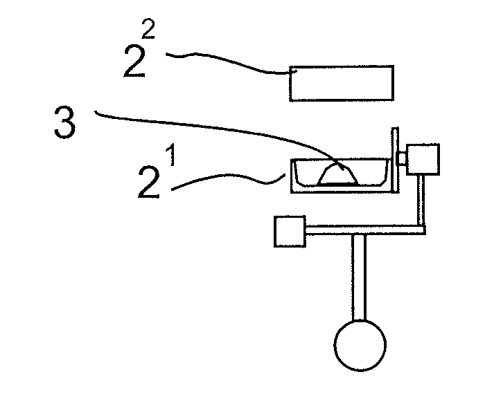
[0024]In the method for fabricating a separation fence 1 to be used in a hydrometallurgical liquid-liquid solvent extraction settler, the fence 1 is manufactured as a shell-like integral piece by rotational moulding.

[0025]A mould 2 composed of two mould halves 21, 22 comprising a first mould half 21 and second mould half 22 is manufactured. The mould halves 21, 22 have walls, the inner surface of which corresponds to the outline of the fence 1. Preferably, the mould halves 21, 22 are made of sheet metal, and thus they have a thin metal wall with a good thermal conductivity.

[0026]As shown in FIG. 1, the mould 2 is supported in a rotation moulding machine so that the mould is rotational about two perpendicular axes. A charge of a polymer resin material powder 3 is poured inside the first mould half 21. The polymer resin material powder 3 may include suitable additives, such as carbon fibers.

[0027]As shown in FIG. 1, the second mould half 22 is installed on the first mould half 21 to c...


PUM

PropertyMeasurementUnit
Shapeaaaaaaaaaa
Widthaaaaaaaaaa
Levelaaaaaaaaaa

Abstract

In a method for fabricating a separation fence (1) to be used in a hydrometallurgical liquid-liquid solvent extraction settler, the fence is manufactured of polymer resin. The fence (1) is manufactured as a shell-like integral piece by rotational moulding. The fence (1) is a rotationally moulded shell-like integral piece.

Description

FIELD OF THE INVENTION[0001]The present invention relates to a method of manufacturing a separation fence to be used in a hydrometallurgical liquid-liquid solvent extraction settler. Further, the invention relates to a separation fence.BACKGROUND OF THE INVENTION[0002]Separation fences are used in a hydrometallurgical liquid-liquid solvent extraction settler to enhance coalescence of the dispersion. In. the VSF® technology (stands for Vertical Smooth Flow) developed by the applicant the separation fences are so-called DDG® fences (Dispersion Depletor Gate) (disclosed e.g. in document U.S. Pat. No. 7,517,461).[0003]In prior art, the separation fence is typically manufactured of a fibre-reinforced plastic composite (FRP) by hand laminating. The fence fabricated by hand lamination has many disadvantages. Hand lamination makes the surfaces of the fence, which are in contact with the liquid flow, rough and the edges sharp so that vortices and dead areas are created in the flow. Sharp edg...

Claims


Application Information

Patent Timeline
IPC IPC(8): B29C39/08B01D11/04B29C33/38
CPCB29C39/08B01D11/04B29C33/38B29C41/06B29C41/04C22B3/02B01D21/2427
Inventor SAARIO, RAMIFREDRIKSSON, HENRI
Owner METSO OUTOTEC (FINLAND) OY
Why Eureka
Try Eureka