
Micro-nano fluid damper

a micro-nano fluid and damper technology, applied in the field of dampers, can solve the problems of consuming a lot of energy for active control, affecting the effect of dampers, so as to enhance the viscosity of fluid and the damping force of dampers, and achieve the effect of enhancing the viscosity of fluid and enhancing the damping for

Active Publication Date: 2015-06-04
NAT APPLIED RES LAB
View PDF5 Cites 7 Cited by
  • Summary
  • Abstract
  • Description
  • Claims
  • Application Information

AI Technical Summary

Benefits of technology

The present invention provides a micro-nano fluid damper that can absorb and transform vibration to thermal energy to be dissipated. It enhances the viscosity and thermal conduction of the micro-nano fluid, thereby having better results of impact absorption. The micro-nano fluid damper has a viscosity that increases with the increasing of shear strain rate when the shear strain rate is larger than the shear thinning threshold and smaller than the shear thickening threshold, and decreases with the increasing of shear strain rate when the shear strain rate is larger than the shear thickening threshold. Overall, the micro-nano fluid damper is effective in absorbing impact and enhancing viscosity.

Problems solved by technology

The impact can directly or indirectly cause damage to the object.
However, active control consumes a lot of energy, and this kind of damper will also be out of function due to power failure.
However, changing the way the damper works by adjusting the electricity still has the problems of durability, voltage life and cost.
Therefore, the cost of this kind of damper is higher than other kinds of damper.
Moreover, the electric / magnetic field generated by the electromagnetic device of the damper is not easy to be evenly distributed, and the arrangement of iron particle is not easy to be controlled either.
Thus, the partial damping force of the damper cannot be controlled accurately, which further influences the damper to show the expected result.

Method used


Image

  • Micro-nano fluid damper
  • Micro-nano fluid damper
  • Micro-nano fluid damper

Examples


Embodiment Construction

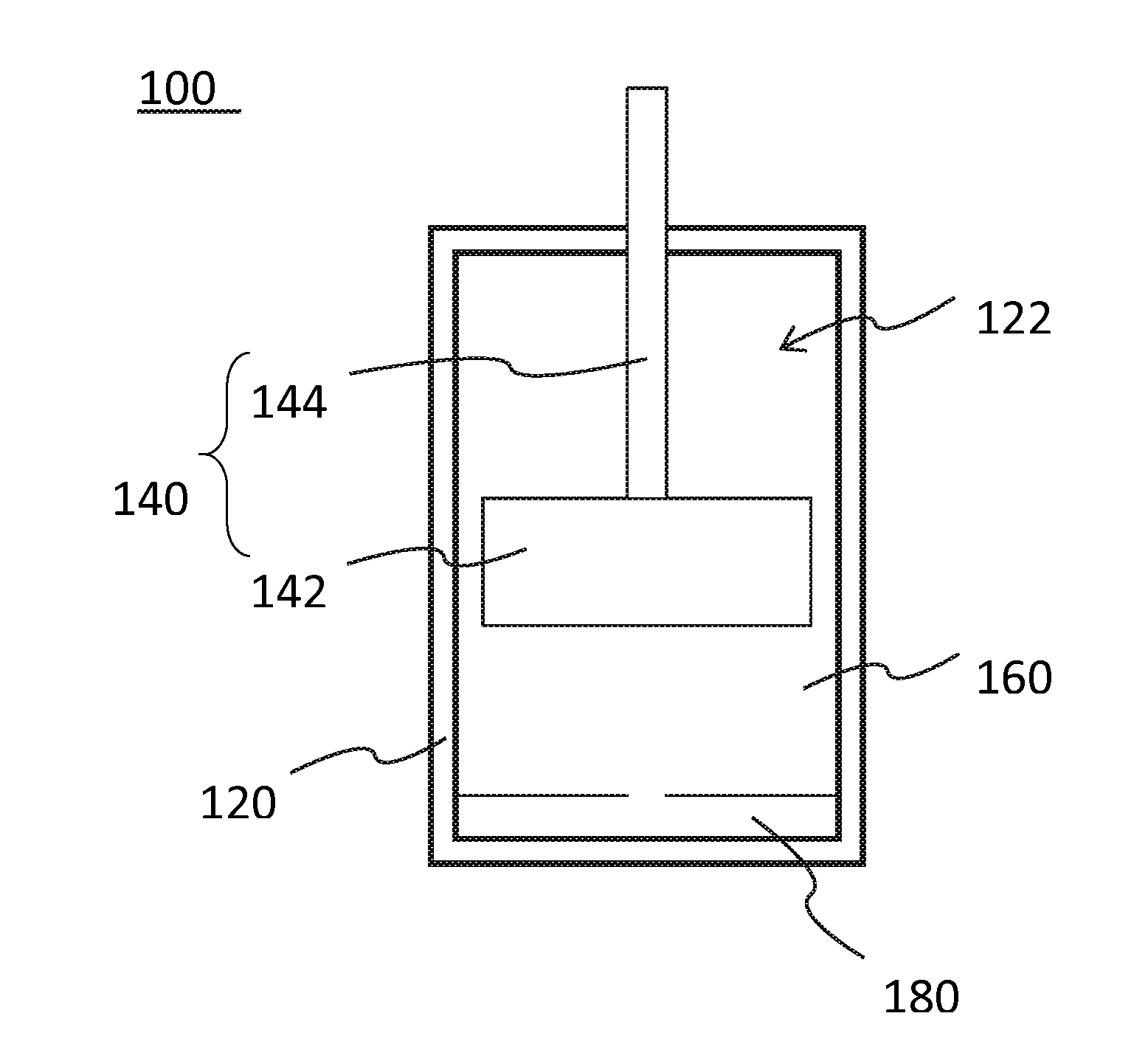
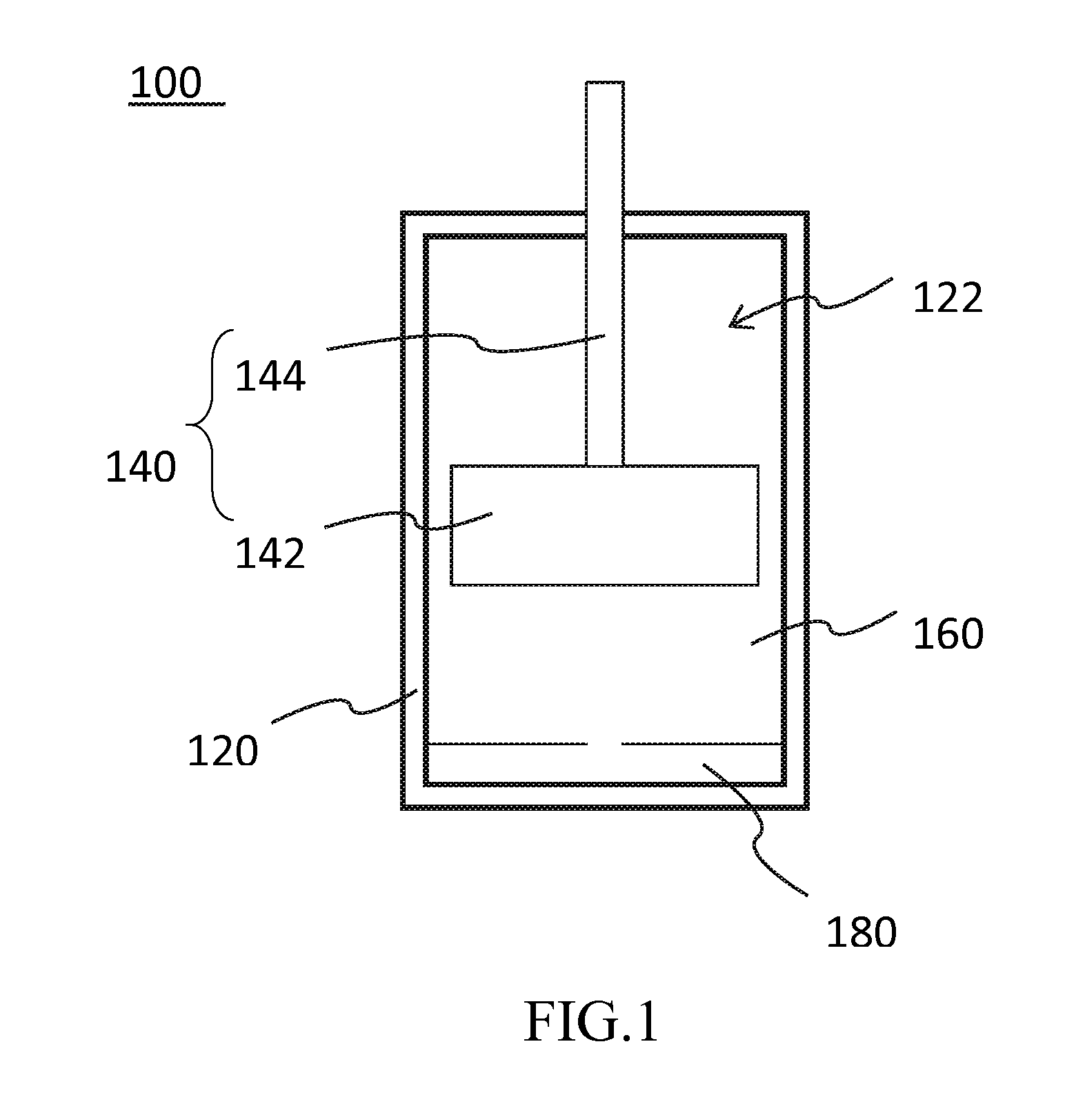
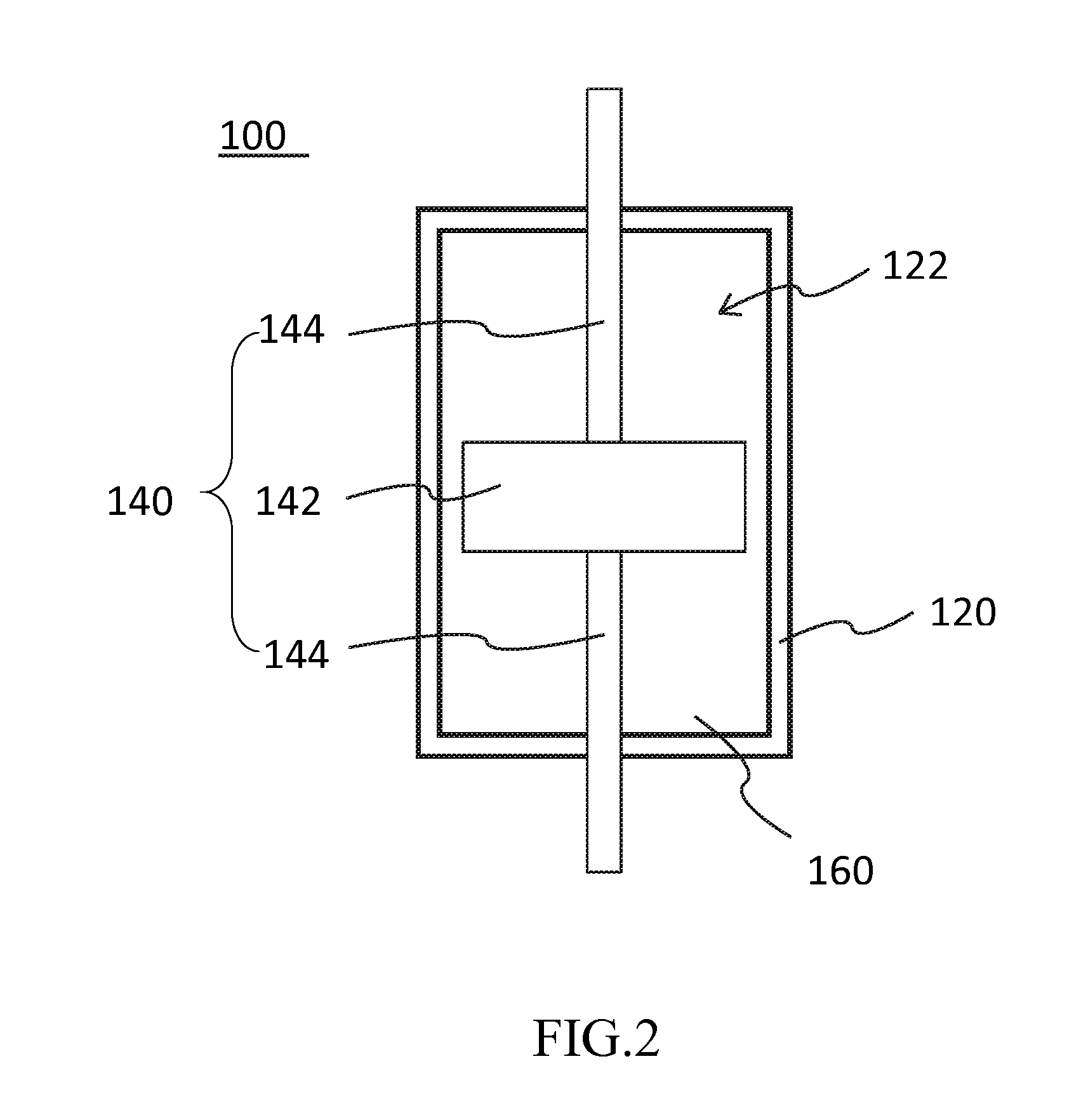
[0054]Please refer to FIG. 1, a micro-nano fluid damper 100 includes a sleeve 120, a piston assembly 140, and a micro-nano fluid 160 filled in the sleeve 120.

[0055]Specifically, the sleeve 120 has an accommodating space 122, and the piston assembly 140 includes a piston head 142 and at least one piston rod 144. The piston assembly 140 can movably be disposed in the accommodating space 122. The piston rod 144 extends out of the sleeve 120 from on side of the piston head 142. The micro-nano fluid 160 is filled between the sleeve 120 and the piston assembly 140. The micro-nano fluid 160 moves back and forth in the accommodating space 122 corresponding to the piston head 142. When a shear strain rate of the micro-nano fluid 160 is greater than 1 s−1, an exponent of velocity of the micro-nano fluid damper 100 is less than 1, and the micro-nano fluid 160 has a shear thinning threshold and a shear thickening threshold. The micro-nano fluid damper 100 in the preferred embodiment of the pres...


PUM


Abstract

A micro-nano fluid damper includes a sleeve, a piston assembly and a micro-nano fluid. The sleeve has an accommodating space. The piston assembly has a piston head and at least one piston rod. The piston assembly is movably disposed in the accommodating space. The piston rod extends out of the sleeve from a side of the piston head. The micro-nano fluid is filled between the sleeve and the piston assembly, and the micro-nano fluid flows in the accommodating space by the back-and-forth movement of the piston. When a shear strain rate of the micro-nano fluid is greater than 1 s−1, an exponent of velocity of the micro-nano fluid damper is less than 1, and the micro-nano fluid has a shear thinning threshold and a shear thickening threshold.

Description

BACKGROUND[0001]1. Technical Field[0002]The present invention relates to a damper, particularly to a damper with micro-nano fluid.[0003]2. Related Art[0004]The function of the conventional damper is for shock absorbing, deceleration, and energy dissipation. When an object moves, no matter linearly or rotatably, impact can be generated. The impact can directly or indirectly cause damage to the object. By installing the damper, the impact can be avoided or minimized, or the mechanical energy generated by the impact can be absorbed.[0005]Most of the conventional dampers in the market are passive vibration dampers, which can be classified as Viscous Damper, Viscoelastic Dampers, Frictional Dampers, and Metal Dampers, etc. Each kind of dampers minimizes the impact caused by vibrating in a way of metal yielding of the damper itself, or by the viscous force of liquid or a solid.[0006]The fluid damper using viscous force of liquid to minimize the impact caused by vibration mainly includes a...

Claims


Application Information

Patent Timeline
IPC IPC(8): F16F9/00F16F9/512F16F9/34F16F9/19F16F9/20
CPCF16F9/006F16F9/19F16F9/512F16F9/3405F16F9/20
Inventor YEH, FANG-YAOCHANG, KUO-CHUNCHEN, TSUNG-WUYU, CHUNG-HAN
Owner NAT APPLIED RES LAB
Learn More