Particulate sensor and method of operation

Inactive Publication Date: 2015-06-04
DELPHI TECH INC
View PDF6 Cites 26 Cited by
  • Summary
  • Abstract
  • Description
  • Claims
  • Application Information

AI Technical Summary

Benefits of technology

[0005]In accordance with one embodiment, a particulate sensing system configured to detect particulates in exhaust gas from a combustion process is provided. The system includes a first electrode, a second electrode, a heater element, and a processor. The second electrode is spaced apart from the first electrode. The particulates are detected based on electrical conductivity between the first electrode and the second electrode. The heater element is configured to heat the first electrode and the second electrode. The first electrode, the second electrode, and the heater element cooperate to form a sensor. The processor is configured to operate the heater element to establish a sensor temperature greater than a dew-point temperature of the exhaust gas and less than a burn-off temperature of the sensor to reduce thermophoretic accumulation of particulates on the sensor.
[0006]In another embodiment, a controller for a particulate sensing system configured to detect particulates in exhaust gas from a combustion process is provided. The system includes a sensor that includes a first electrode, a second electrode spaced apart from the first electrode, and a heater element configu

Problems solved by technology

If this voltage is increased, the rate of accumulation of particulates generally increases.
If the sensor temperature of the sensor is less than the dew-point of the exhaust gas, it is undesirable to collect particulates by way of electrophoretic accumulation as condensation may cause the accumulated particulates to be wet or otherwise con

Method used


Image

  • Particulate sensor and method of operation
  • Particulate sensor and method of operation
  • Particulate sensor and method of operation

Examples


Embodiment Construction

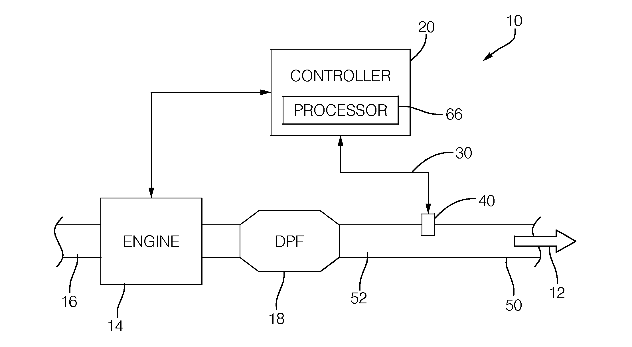
[0014]FIG. 1 illustrates a non-limiting example of a particulate sensing system, hereafter referred to as the system 10. In general, the system is configured to detect particulates in an exhaust gas 12 from a combustion process. In this non-limiting example the combustion process is the operation of an internal combustion engine, hereafter referred to as the engine 14. However, it is recognized that the combustion process could be the burning of coal or other fuels in an industrial oven, boiler, reactor, or the like. The configuration of the engine 14 shown in FIG. 1 is not particularly limited. The engine 14 may include a plurality of cylinders (two or more cylinders, for example, four cylinders or six cylinders) that are arranged in various ways (e.g., in-line or V-type) as will be recognized by those in the art.

[0015]An intake port of the internal combustion engine 14 is in fluidic communication with an intake 16. The intake 16 is provided as needed, for instance, with various pi...


PUM


Abstract

A particulate sensing system configured to detect particulates in exhaust gas from a combustion process. Particulates are detected based on electrical conductivity between a first electrode and a second electrode. A heater element is provided to heat the first electrode and the second electrode. The first electrode, the second electrode, and the heater element cooperate to form a sensor. The heater element is operated to establish a sensor temperature greater than a dew-point temperature of the exhaust gas and less than a burn-off temperature of the sensor to reduce thermophoretic accumulation of particulates on the sensor. When the exhaust temperature and the sensor temperature are suitable for thermophoretic accumulation and electrophoretic accumulation of particulates, a voltage is applied across the electrodes to facilitate electrophoretic accumulation of particulates, and the heater element is turned off so thermophoretic accumulation occurs.

Description

TECHNICAL FIELD OF INVENTION[0001]This disclosure generally relates to an exhaust particulate sensor, and more particularly relates to heating the sensor during certain conditions to reduce thermophoretic accumulation of particulates on the sensor.BACKGROUND OF INVENTION[0002]Particulate Matter (PM) sensors are used in exhaust systems of many diesel engines to diagnose the operational status of a Diesel Particulate Filter (DPF). Typically, the sensor has adjacent electrodes that define a gap, and particulates accumulate in a gap in between the electrodes. Since the particulates are generally conductive, the measured resistance between the electrodes of the sensor will decrease as particulates accumulate. If the DPF is allowing too many particulates to pass, the rate that particulates will accumulate in the gap will increase.[0003]While not subscribing to any particular theory, there are believed to be three main mechanisms by which particulates accumulate on the sensor: electrophore...

Claims


Application Information

Patent Timeline
IPC IPC(8): G01M15/10
CPCG01M15/102F02D41/1466G01N2015/0046G01N15/0606G01N15/0656
Inventor GOULETTE, DAVID A.HOCKEN, LARY R.
Owner DELPHI TECH INC
Why Eureka
Try Eureka