
Tactile low frequency transducer

a low frequency transducer and transducer technology, applied in the field of media systems, can solve the problems of insufficient reproduction of lower frequencies, earphones and portable speakers that do not provide satisfactory sensory experience, and often lose low frequency (bass) components of music, etc., to achieve enhanced musical experience and increase sound reproduction fidelity

Active Publication Date: 2015-06-04
WOOJER
View PDF8 Cites 25 Cited by
  • Summary
  • Abstract
  • Description
  • Claims
  • Application Information

AI Technical Summary

Benefits of technology

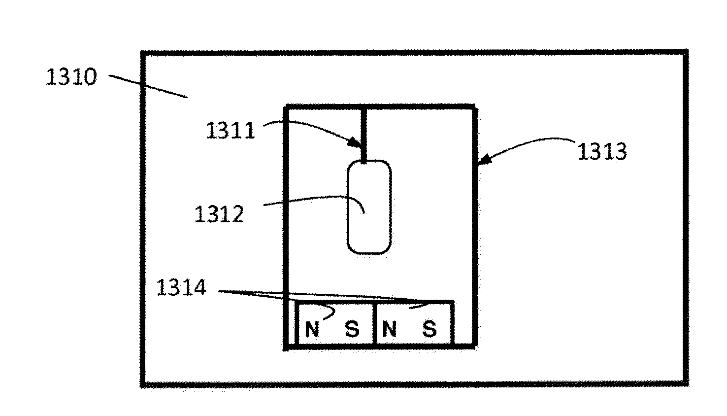
The present invention is about improving the sound reproduction of devices described in previous patent applications. The invention involves a transducer consisting of a flat strip of metal that is formed into a closed metal loop with rounded corners. The loop has a continuously varying width on at least one of its sides. The transducer is fixed with a solenoid and magnets to vibrate over a range of frequencies in response to a signal with varying frequencies. The stiffener reduces distortion and improves flexing of the sections of the metal loop. The result is an enhanced musical experience.

Problems solved by technology

However, the large variety of personal media playing systems that is available to today's media consumer does not.
In personal systems, the low frequency (bass) components of music is often lost.
Although such earphones and small speakers adequately provide vocal and melody (mid frequencies), they do not adequately reproduce lower frequencies which are not picked up by the ear-drum, but rather through the body vibrating, particularly the thorax and diaphragm.
Consequently, earphones and portable speakers do not provide a satisfactory sensory experience that is analogous to that experienced in a night club, or theater during a live performance by a big orchestra or a rock band.
Conventional bass speakers, commonly known as sub woofers, are large and bulky.
Personal music systems, whether small speakers on MP3s and smart-phones, or earphones and earplugs do not provide the bass experience.
However, such frequencies require very big speakers to reproduce.
To allow high amplitude of vibration, this arrangement requires high power consumption.
The actuator thus does not provide good sound reproduction, and has poor fidelity.

Method used


Image

  • Tactile low frequency transducer
  • Tactile low frequency transducer
  • Tactile low frequency transducer

Examples


Embodiment Construction

[0077]The present embodiments comprise an apparatus and a method for personal media playing.

[0078]According to an exemplary embodiment of the present invention, there is received a media signal, say an audio signal of a piece of music or of a soundtrack of a movie, a signal of a video clip encoded in an MP4 format, a video stream, etc.

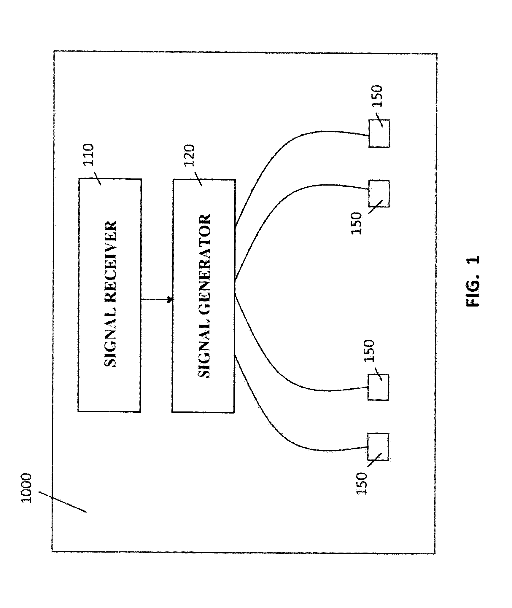
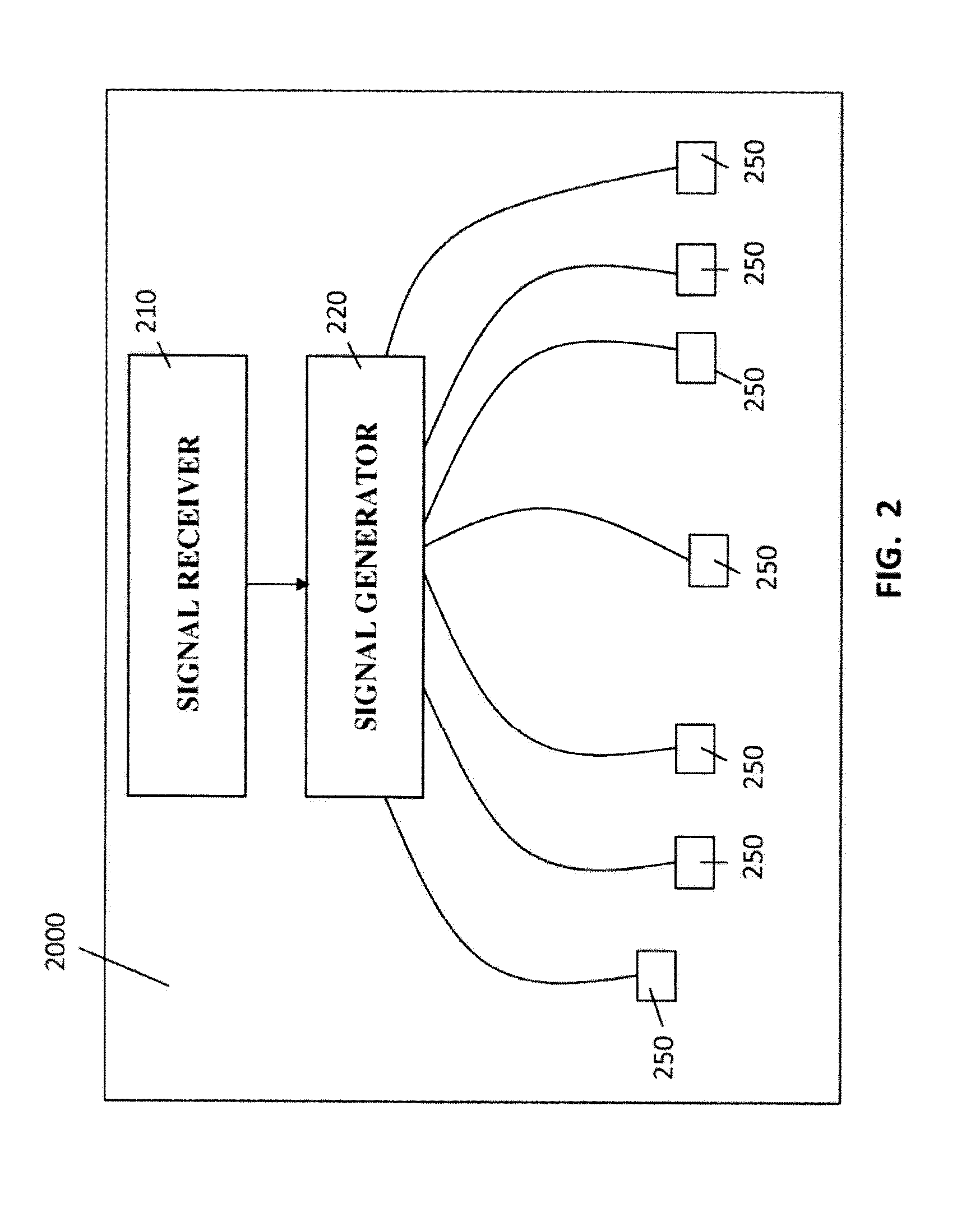
[0079]Then, there are derived two or more signals, say low frequency signals, from the media signals. The derived signals may be similar, or different from each other. Each of the derived signals is destined for a specific body area of the user, as described in further detail hereinbelow.

[0080]In one embodiment of the present invention, each of the derived signals is tailored for the specific body area of a user, which the derived signal is destined for, say using a dedicated processor chip, as described in further detail hereinbelow.

[0081]For example, one of the signals derived from the media signal, may be tailored for a specific body area in which b...


PUM


Abstract

A transducer comprising: a flat strip of metal formed into a closed metal loop with two substantially parallel sides and rounded corners, a solenoid fixed to a surface on a first parallel side, and fixed magnets attached to an opposite parallel side of the trapezoidal shape to bring the fixed magnets into proximity with the solenoid, wherein at least one lateral side of the trapezoidal shape coupling said parallel sides has a continuously varying width, resulting in the transducer being able to resonate with high fidelity over a range of frequencies in response to reception of a signal comprising varying frequencies.

Description

PRIORITY INFORMATION[0001]This application is a continuation of U.S. Ser. No. 13 / 819,086, filed May 7, 2013, and in addition claims priority for additional subject matter to U.S. Ser. No. 13 / 819,049, filed May 8, 2013. The subject application also claims priority to U.S. Provisional Application No. 61 / 378,983 filed on Sep. 1, 2010; U.S. Provisional Application No. 61 / 427,150 filed on Dec. 24, 2010; U.S. Provisional Application No. 61 / 452,649 filed on Mar. 15, 2011; PCT / IB2011 / 053233, filed Jul. 20, 2011; and, PCT Application No: PCT / IB2011 / 053765, filed Aug. 28, 2011.FIELD AND BACKGROUND OF THE INVENTION[0002]The present invention relates to media systems, more particularly, but not exclusively to a personal media playing system.[0003]Hi-Fi systems adequately reproduce audible frequencies. However, the large variety of personal media playing systems that is available to today's media consumer does not.[0004]Among widely used personal media playing systems are MP3 players, portable D...

Claims


Application Information

Patent Timeline
Patent Type & Authority Applications(United States)
IPC IPC(8): H04R1/28H02K33/16
CPCH02K33/16H04R1/2803
Inventor EFRATI, MOR
Owner WOOJER
Learn More