
Radiation detecting apparatus and radiation tomographic imaging apparatus

Active Publication Date: 2015-06-04
GENERAL ELECTRIC CO
View PDF5 Cites 9 Cited by
  • Summary
  • Abstract
  • Description
  • Claims
  • Application Information

AI Technical Summary

Benefits of technology

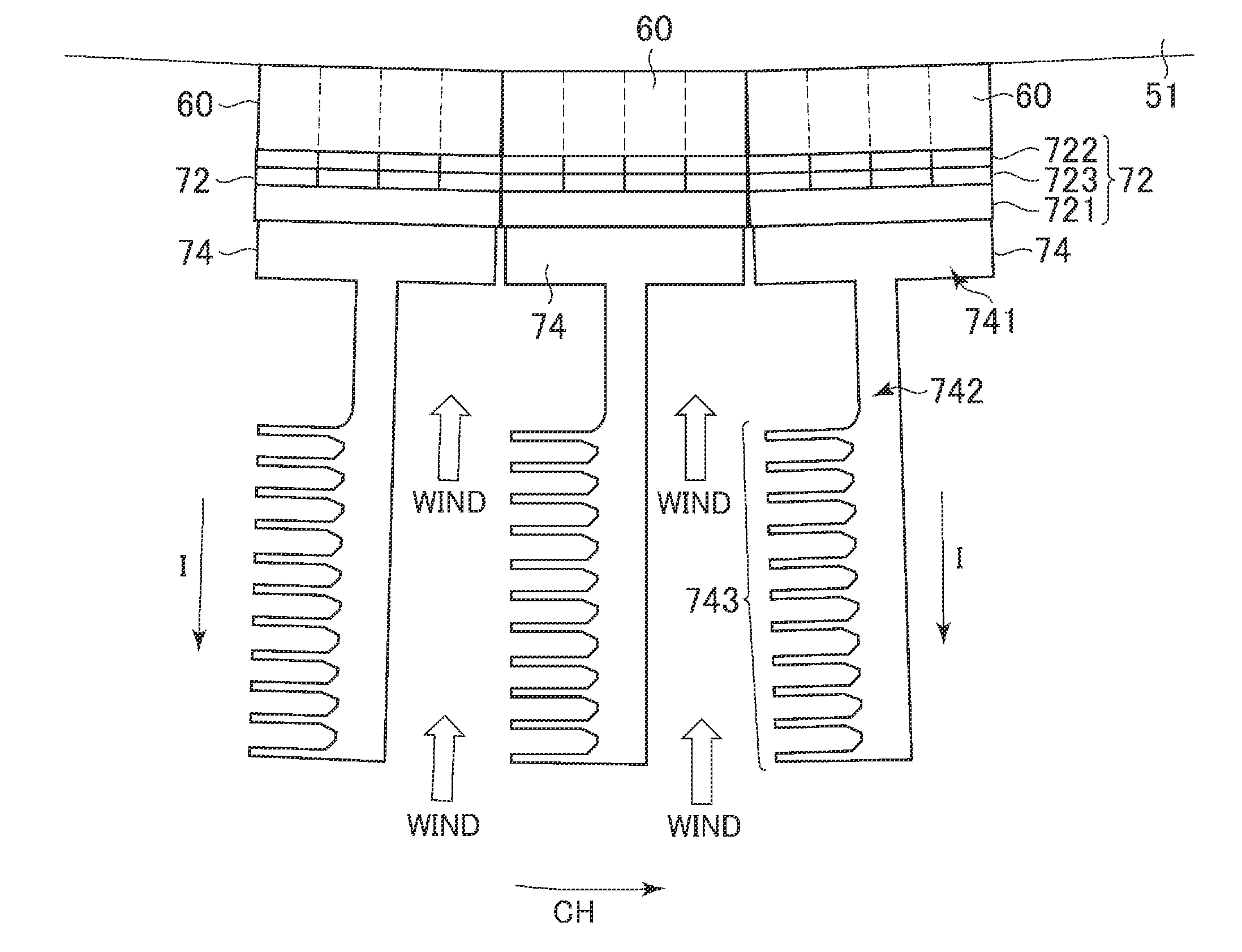
The invention aims to provide a technology to cool down each detecting element in a radiation detecting apparatus and stabilize detection characteristics. The first wind shielding unit prevents wind from affecting the detecting element during rotation of the gantry, while the second wind shielding unit prevents blown wind from directly hitting the detecting element. This results in more efficient air cooling of each detecting element, suppressing temperature changes and achieving stable radiation detection.

Problems solved by technology

Therefore, the heat is liable to be conducted to the detecting elements, and the control on the temperature of each detecting element often won't go as hoped in the cooling system.
Therefore, when the rotational speed of the gantry rotating section is changed, the temperature of the detecting element is also liable to change.
That is, the cooling method using the cooling fan is not capable of sufficiently suppressing the change in the temperature of the detecting element and is difficult to achieve the stabilization of the detection characteristics.

Method used


Image

  • Radiation detecting apparatus and radiation tomographic imaging apparatus
  • Radiation detecting apparatus and radiation tomographic imaging apparatus
  • Radiation detecting apparatus and radiation tomographic imaging apparatus

Examples


Embodiment Construction

[0015]A preferred embodiment of the present invention will hereinafter be described. Incidentally, the present invention is not limited to or by the present embodiment.

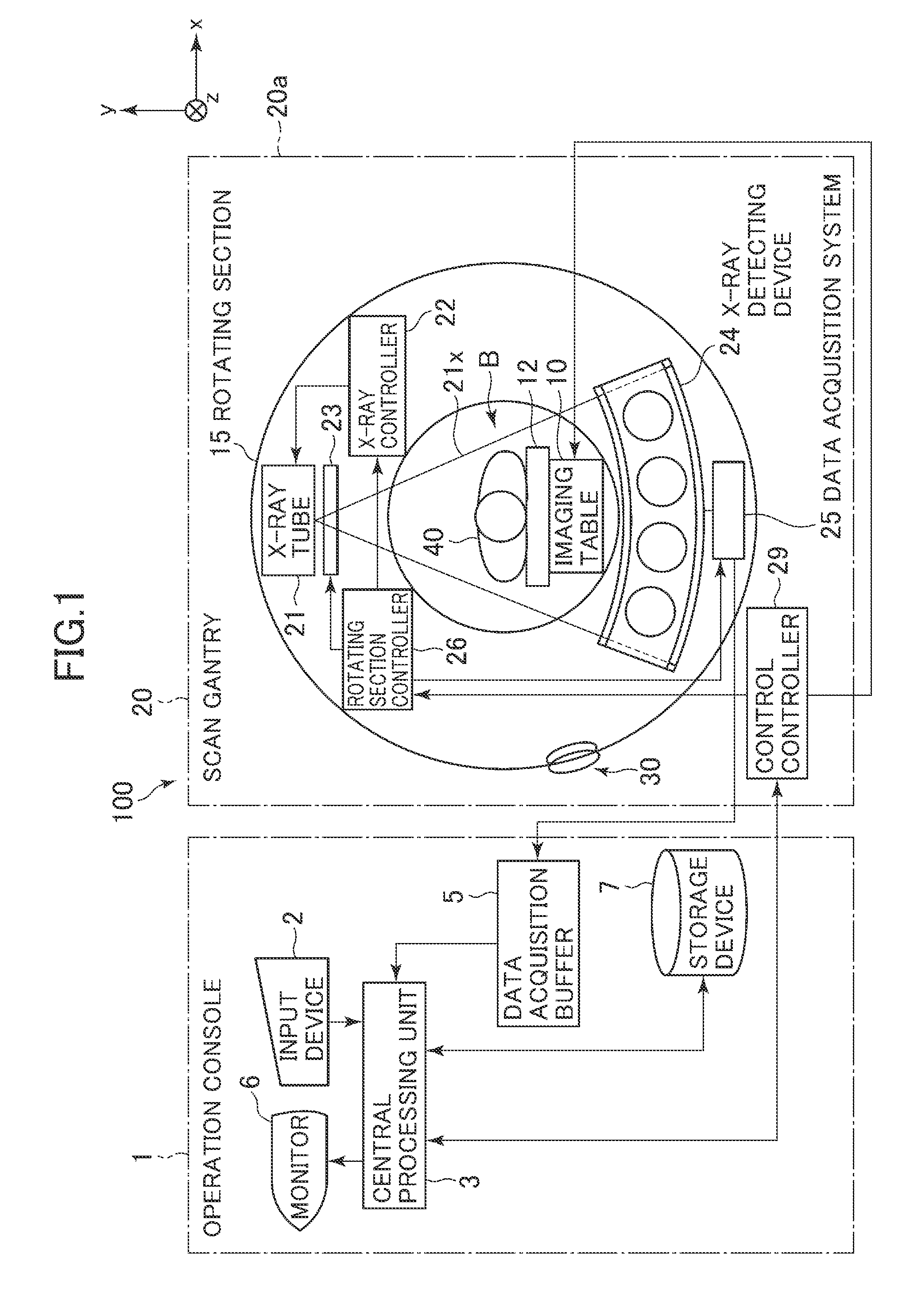
[0016]FIG. 1 is a diagram schematically showing a configuration of an X-ray CT (Computed Tomography) apparatus according to the embodiment of the present invention. As shown in FIG. 1, the X-ray CT apparatus 100 is equipped with an operation console 1, an imaging table 10 and a scan gantry 20.

[0017]The operation console 1 is equipped with an input device 2 which accepts an input from an operator, a central processing unit 3 which performs control of respective parts for performing imaging of a subject 40 to be imaged, a data process for generating an image, etc., a data acquisition buffer 5 which acquires data acquired by the scan gantry 20, a monitor 6 which displays an image thereon, and a storage device 7 which stores a program, data, etc. therein.

[0018]The imaging table 10 is equipped with a cradle 12 which insert...


PUM


Abstract

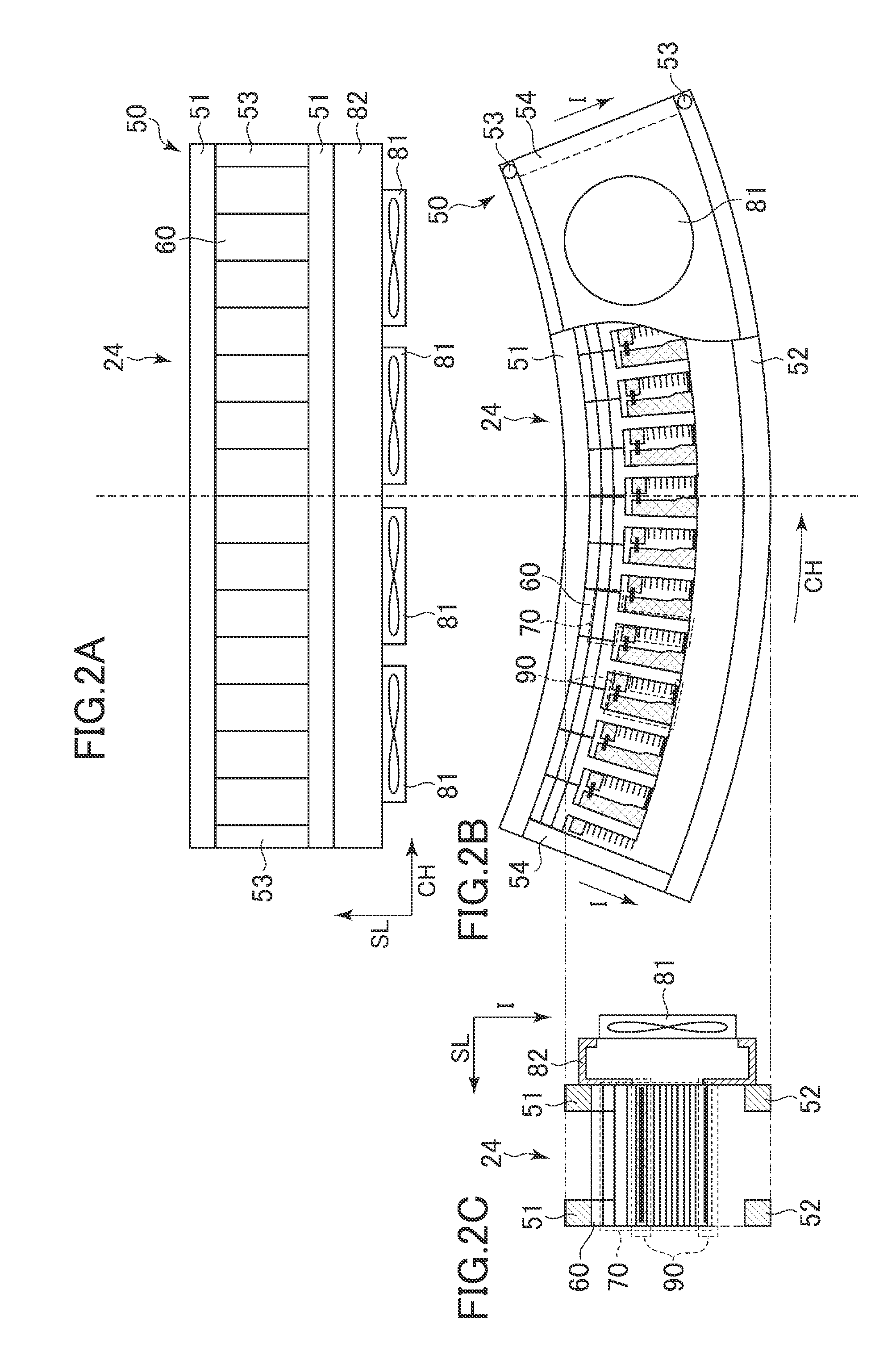
A radiation detecting apparatus is provided. The radiation detecting apparatus includes a plurality of detector modules arranged in a channel direction, each detector module including a plurality of detecting elements arranged in matrix form in the channel direction and a slice direction, and a heat radiating unit thermally coupled to the detecting elements and provided on an X-ray outgoing side of the detecting elements, a wind blowing unit configured to send wind to the heat radiating units of the detector modules in the slice direction, first wind shielding portions provided on a radiation outgoing side of the heat radiating units and configured to shield the wind in a radiation irradiating direction, and second wind shielding portions provided on a radiation incoming side of the heat radiating units and configured to shield the wind in the radiation irradiating direction.

Description

BACKGROUND OF THE INVENTION[0001]The present invention relates to a technology which stabilizes radiation detection characteristics of a radiation tomographic imaging apparatus.[0002]It has been known that the radiation detection characteristics of a radiation tomographic imaging apparatus depend on the temperature of a detecting element in a radiation detecting apparatus therefor, particularly a photoelectric conversion element. On the other hand, the temperature of the detecting element has a strong tendency to gradually increase due to the generation of heat of electrical / electronic components disposed around the detecting element. Therefore, generally, a cooling system is provided in the radiation detecting apparatus to cool heating components or the like and control the temperature of a detecting element to be kept constant as much as possible, thereby achieving stabilization of the radiation detection characteristics.[0003]As the cooling system mentioned above, an air cooling ...

Claims


Application Information

Patent Timeline
IPC IPC(8): H05K7/20G01N23/04G01T1/20
CPCH05K7/20163G01N23/046H05K7/20145G01T1/20A61B6/032A61B6/4488
Inventor KAWAGUCHI, KOTATSULACEY, JOSEPH JAMESVANDEWEGHE, RICHARD PAUL
Owner GENERAL ELECTRIC CO
Learn More