Demister Apparatus and Method

a technology of demister apparatus and cylinder, which is applied in the direction of filtration separation, auxillary pretreatment, separation process, etc., can solve the problems of health hazards, maintenance burden, air pollution problems, etc., and achieve the effect of reducing the total power consumption of the fan motor, reducing the power consumption required, and reducing the rate of air flow

Inactive Publication Date: 2015-06-11
FILTRA SYSTEMS COMPANY
View PDF36 Cites 14 Cited by
  • Summary
  • Abstract
  • Description
  • Claims
  • Application Information

AI Technical Summary

Benefits of technology

[0012]It is an object of the present invention to provide a demister arrangement for machine tool installations which greatly reduces the power consumption required while insuring that no mist escapes from the machining booth at any time.
[0013]The above recited object as well as other objects which will be understood by those skilled in the art upon a reading of the following specification and claims is achieved by reducing the rate of air flow drawn from the machining booth to that minimally necessary to insure that no mist escapes the machine tool booth. This is achieved by varying the volume of air flow drawn out from the booth to a low level which is all that will be needed during those periods when the access doors to the machining center booth enclosure are closed, to a maximum air flow drawn from the booth when the doors are opened, as when loading and removing parts being machined in the statio...

Problems solved by technology

This spraying creates a fine mist which is intended to be confined within the booth in order to prevent the mist from being dispersed into the air within the plant, where it could be inhaled by plant personnel and present a health hazard.
Also, the mist can condense onto adjacent surfaces, creating a maintenance burden.
Oil in the coolant/lubricant can also evaporate from the mist into the air and create an air pollution problem.
This is because leaking of condensed mist from the ducting, and evaporation of the oil in the mist into the air can both occur in t...

Method used


Image

  • Demister Apparatus and Method
  • Demister Apparatus and Method
  • Demister Apparatus and Method

Examples


Embodiment Construction

[0027]In the following detailed description, certain specific terminology will be employed for the sake of clarity and a particular embodiment described in accordance with the requirements of 35 USC 112, but it is to be understood that the same is not intended to be limiting and should not be so construed inasmuch as the invention is capable of taking many forms and variations within the scope of the appended claims.

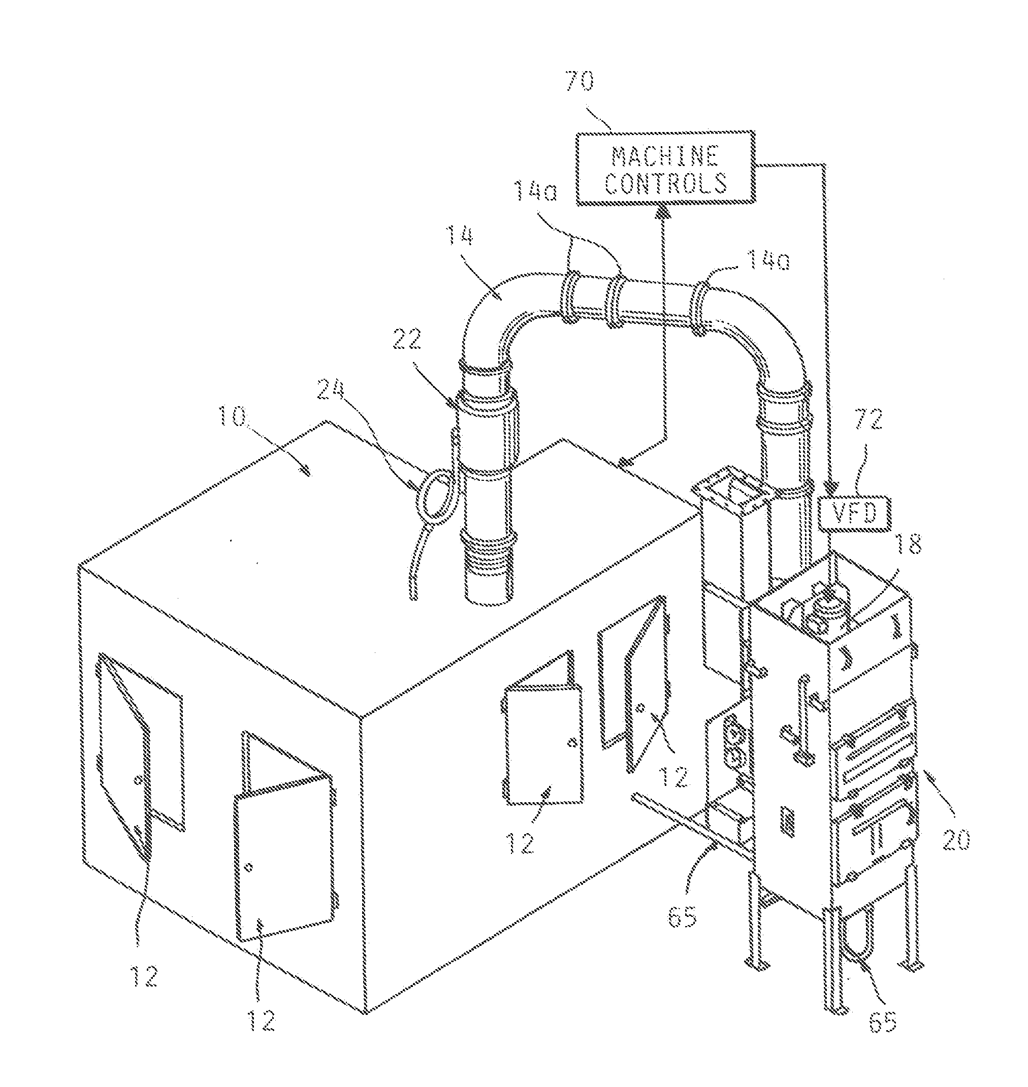
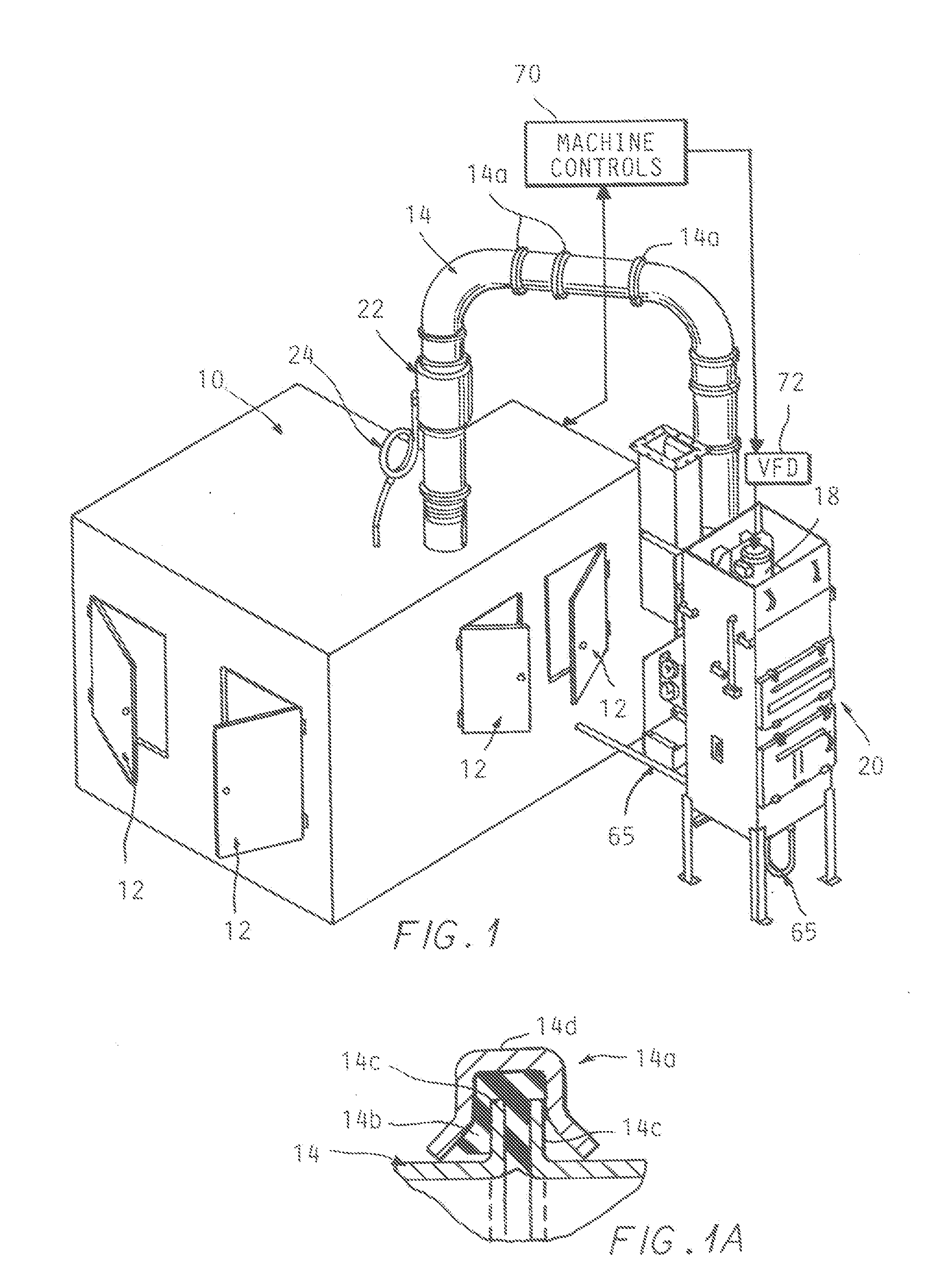
[0028]Referring to FIG. 1, a machining center booth 10 is shown which encloses a conventional automated CNC machining station (not shown) in which parts are machined with the use of metal cutting tools in the well known manner.

[0029]The parts are typically unloaded after one or more access door panels 12 are opened, as indicated in FIG. 1 by load / unload robots or other part handling devices (not shown), which then load parts to be machined into the machines, with the access door panels then closed.

[0030]As noted, such machining operations use metal cutting tools which in...


PUM

PropertyMeasurementUnit
Pressureaaaaaaaaaa
Poweraaaaaaaaaa
Flow rateaaaaaaaaaa

Abstract

A demister apparatus for machine tools having an enclosure booth for confining mist in which a varying outflow of air is drawn from the booth and directed to a remote demister apparatus from a minimum when the access doors to the enclosure are closed to a maximum when one or more of the doors are opened. The air flow may also be varied with the number of machine tools in operation as well with the state of filters in the remote demister apparatus. A cyclonic separator is also provided adjacent to the booth which functions well in a vertical up flow mode over a range of air outflow rates of flow.

Description

CROSS REFERENCE TO RELATED APPLICATIONS[0001]This application claims the benefit of U.S. provisional application Ser. No. 61 / 913,553 filed on Dec. 9, 2013.BACKGROUND OF THE INVENTION[0002]In automated machining of parts such as engine components, the machining takes place at machine stations, each station enclosed to form a booth. A coolant / lubricant liquid is sprayed onto the part during the machining operations in order to reduce friction and cool the part.[0003]This spraying creates a fine mist which is intended to be confined within the booth in order to prevent the mist from being dispersed into the air within the plant, where it could be inhaled by plant personnel and present a health hazard. Also, the mist can condense onto adjacent surfaces, creating a maintenance burden.[0004]Oil in the coolant / lubricant can also evaporate from the mist into the air and create an air pollution problem.[0005]In order to minimize this effect, the conventional practice has been to constantly d...

Claims


Application Information

Patent Timeline
IPC IPC(8): B01D46/44B01D46/00
CPCB01D46/0027B01D46/446B01D45/12B01D46/003B01D2273/30B01D50/20B01D45/06B04C3/00B04C3/06B01D46/0086B01D45/08B01D46/0002B01D45/16
Inventor BRATTEN, KEITHBRATTEN, SCOTT
Owner FILTRA SYSTEMS COMPANY
Why Eureka
Try Eureka