Object Of Additive Manufacture With Encoded Predicted Shape Change And Method Of Manufacturing Same

Inactive Publication Date: 2015-06-11
MASSACHUSETTS INST OF TECH +1
View PDF9 Cites 52 Cited by
  • Summary
  • Abstract
  • Description
  • Claims
  • Application Information

AI Technical Summary

Benefits of technology

[0005]Existing 3D printing technologies hold a promise of an ability to mass-produce customized components by substantially reducing the time and materials necessary, which can consequently increase efficiency

Problems solved by technology

However, in some cases existing technology may still require additional processes, for example labor-in

Method used


Image

  • Object Of Additive Manufacture With Encoded Predicted Shape Change And Method Of Manufacturing Same
  • Object Of Additive Manufacture With Encoded Predicted Shape Change And Method Of Manufacturing Same
  • Object Of Additive Manufacture With Encoded Predicted Shape Change And Method Of Manufacturing Same

Examples


example 1

Formation of a Cube

[0123]In this example, a generally cylindrical object transforms into a first generation of a fractal Hilbert curve in the shape of a cube.

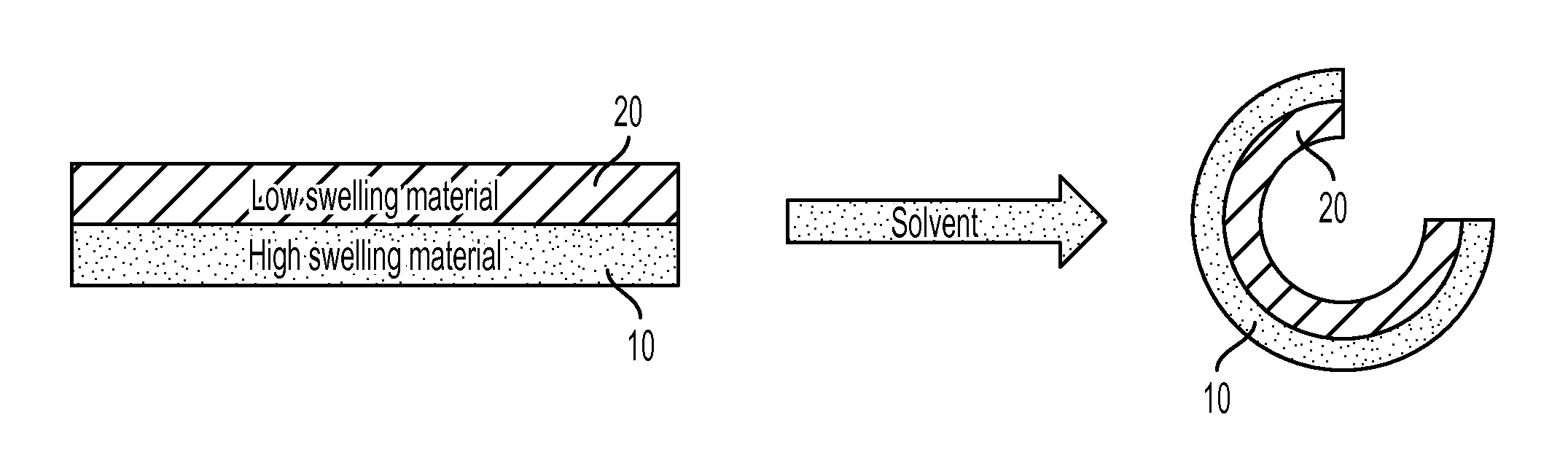
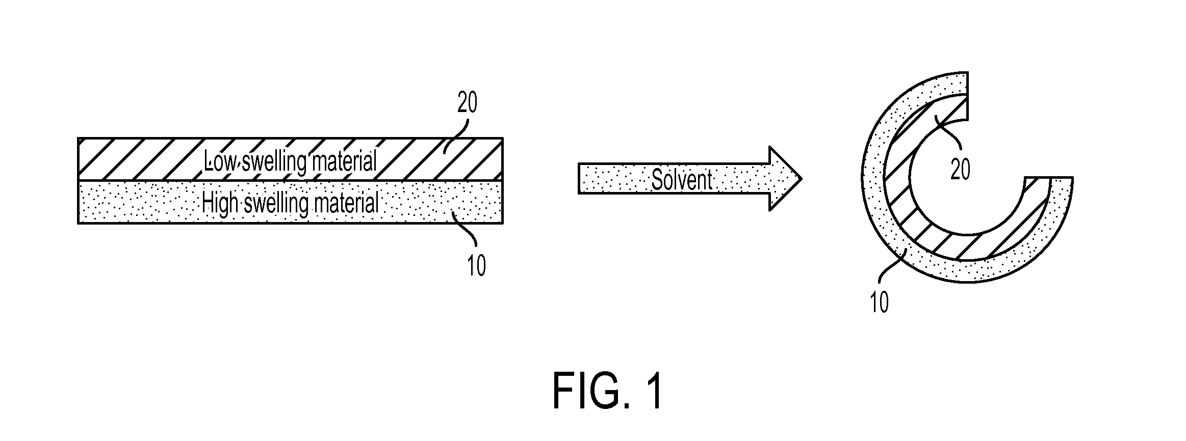
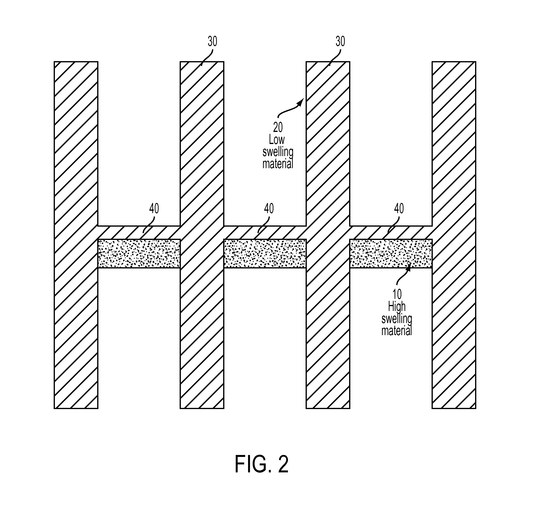
[0124]FIG. 2 is a schematic representation of an arrangement of a low swelling material and a high swelling material that can form a folding joint. The object has a generally cylindrical shape. Two cylindrical discs 30 are spaced apart by a horizontal member 40. The high swelling material 10 is placed on one side of the horizontal member 40. The cylindrical discs 30 and horizontal members 40 are made of a low swelling material. For example, the high swelling material can be more hydrophilic than the low swelling material. Stated differently, the low swelling material can be more hydrophobic than the high swelling material. The cylindrical discs 30 function as angle limiters. Upon exposure to an external stimulus, the cylindrical discs 30 force the joint to fold to an approximately 90° angle. In order to change the curvature of ...

example 2

Transformation from a Cylinder to Letters

[0129]In this example, a generally cylindrical object transforms into a series of letters that spell “MIT.”

[0130]FIG. 6 is a table having four columns that: A) describe a type of joint; B) provide a computer aided design (CAD) of the joint; C) show an experimental representation of the joint after exposure to an external stimulus; and D) illustrate a simulation showing the predicted shape of the joint after exposure to an external stimulus. Each of the joints in FIG. 6 can be used to curve an object of additive manufacture upon exposure to an external stimulus. Each of the joints has a different arrangement of high swelling material 10 and low swelling material 20, and thus each joint curves differently, as are illustrated in the experimental and simulated curvature (columns C and D). The joint designated Elbow-“bi” is particularly effective for creating larger curvatures, though each of the joints listed, as well as modifications and hybrids...

example 3

Formation of a Cube with Solid Sides

[0134]This example demonstrates surface transformations. A two-dimensional flat plane was printed. The flat plane corresponds to the six unfolded surfaces of a cube. At each of the joints, a strip of high and low swelling material is arranged so that the object transforms from a first shape to a second shape upon exposure to an external stimulus. The arrangement of high and low swelling material at each joint enables a 90° curvature so that the faces of the cube curve toward each other and stop curving upon reaching the second, predetermined shape. When submerged in water, the first shape transforms into a closed surface cube with filleted edges.

[0135]FIGS. 9A-F are schematic representations of an object of additive manufacture that can transform into a cube having solid sides after exposure to an external stimulus. FIG. 9A is a top view of the object, which is formed from six panels 320, one for each face of the cube, with joints that fold upon e...


PUM

PropertyMeasurementUnit
Glass transition temperatureaaaaaaaaaa

Abstract

The combination of 3D printing technology plus the additional dimension of transformation over time of the printed object is referred to herein as 4D printing technology. Particular arrangements of the additive manufacturing material(s) used in the 3D printing process can create a printed 3D object that transforms over time from a first, printed shape to a second, predetermined shape.

Description

RELATED APPLICATION(S)[0001]This application claims the benefit of U.S. Provisional Application No. 61 / 930,521, filed on Jan. 23, 2014. This application also claims the benefit of U.S. Provisional Application No. 61 / 912,056, filed on Dec. 5, 2013. The entire teachings of the above applications are incorporated herein by reference.COMMON OWNERSHIP UNDER JOINT RESEARCH AGREEMENT 35 U.S.C. 102(c)[0002]The subject matter disclosed in this application was developed, and the claimed invention was made by, or on behalf of, one or more parties to a joint Research Agreement that was in effect on or before the effective filing date of the claimed invention. The parties to the Joint Research Agreement are the Massachusetts Institute of Technology, located in Cambridge, Mass., USA; and Stratasys Ltd., an Israeli company located at 2 Holzman Street, Rehovot, Israel 76124, and Stratasys, Inc., a Delaware corporation located at 7665 Commerce Way, Eden Prairie, Minn. 55344 (collectively, “Stratasys...

Claims


Application Information

Patent Timeline
IPC IPC(8): B29C61/00C08F20/28C08G65/26C08F20/30C08L33/08C08F20/18C08L33/14C08L71/02C08L35/02B29C67/00C08F22/10
CPCB29C61/003B33Y80/00B29C67/0085B29C67/0088C08F20/28C08G65/2609C08F20/30C08F22/105C08F20/18C08L33/14C08L71/02C08L35/02C08L33/08B29K2033/04B29K2071/02B33Y10/00B33Y30/00B33Y50/02B33Y70/00B29C67/0051B29C69/025C08F220/20B29C64/386Y10T403/32Y10T403/32606Y10T403/32975Y10T428/31913C08F222/1067B29K2995/0049B29K2105/02B29L2031/5281B29C61/02B29C71/0009B29K2033/08B29L2031/529B29C64/112B29C61/04B29L2031/22B29C64/106
Inventor TIBBITS, SKYLAR J.E.DIKOVSKY, DANIELHIRSCH, SHAI
Owner MASSACHUSETTS INST OF TECH
Why Eureka
Try Eureka