Detection device, sensor, electronic apparatus and moving object

a detection device and electronic equipment technology, applied in turn-sensitive devices, instruments, machines/engines, etc., can solve the problems of mechanical vibration, large amount of signal delay in the signal band, and unnecessary signal of the detuning frequency due to mechanical vibration, so as to prevent signal delay and effectively attenuate a component of the detuning frequency

Active Publication Date: 2015-06-11
SEIKO EPSON CORP
View PDF11 Cites 17 Cited by
  • Summary
  • Abstract
  • Description
  • Claims
  • Application Information

AI Technical Summary

Benefits of technology

[0011]An advantage of some aspects of the invention is to provide a detection device, a sensor, an electronic apparatus, a moving object, and the like capable of effectively attenuating a component of a detuning frequency while preventing signal delay or the like.
[0013]According to this aspect of the invention, the drive circuit drives the vibrator, and the detection circuit performs the detection and outputs the detection data. Further, the digital signal processing unit performs the band elimination filtering for attenuating the component of the detuning frequency as the digital filtering for the detection data. If such a band elimination filter is used, by setting a center frequency of the band elimination filter to a frequency corresponding to the detuning frequency, it is possible to efficiently attenuate the component of the detuning frequency. Further, if the band elimination filter is used, it is possible to prevent signal delay or the like in a signal band, compared with a method for removing the unnecessary signal of the detuning frequency by a high-order low pass filter or the like. Accordingly, it is possible to provide the detection device capable of effectively attenuating the component of the detuning frequency while preventing the signal delay or the like.
[0017]With such a configuration, even when characteristics of the respective detuning frequencies of the respective plural vibrators are different from each other, by storing each filter coefficient based on the characteristic of each detuning frequency in the storage unit, it is possible to handle the problem.
[0021]With such a configuration, it is possible to reduce the circuit size, compared with a method for performing band elimination filtering by providing plural multipliers and plural adders. Further, for example, by employing a pipeline method for simultaneously operating the multipliers and the adders, it is possible to suppress the number of sequences of the band elimination filtering to the minimum.
[0023]With such a configuration, an external processing unit or the like can obtain output data corresponding to the detection data at a timing that does not depend on the output timing of the detection data of the digital signal processing unit. Further, if such re-sampling of the output data is performed, the component of the unnecessary signal of the detuning frequency is folded into the signal band to reduce the detection performance, but by performing the band elimination filtering, such a problem can be prevented.

Problems solved by technology

In such a vibration gyro sensor, an unnecessary signal of a detuning frequency due to mechanical vibration such as a disturbance is generated.
However, if a low pass filter with a low cutoff frequency is used in order to remove the unnecessary signal of the detuning frequency, a signal band becomes narrow.
Further, in order to attenuate the component of the detuning frequency by increasing the cutoff frequency to secure the signal band, a high-order filter is necessary, which causes a large amount of signal delay in the signal band.
In addition, in a method for generating the detuning frequency signal of the same frequency as that of the unnecessary signal of the detuning frequency and then subtracting the signal from the original signal, a circuit becomes complicated, and a circuit size becomes large, which increases the cost.

Method used


Image

  • Detection device, sensor, electronic apparatus and moving object
  • Detection device, sensor, electronic apparatus and moving object
  • Detection device, sensor, electronic apparatus and moving object

Examples


Embodiment Construction

[0052]Hereinafter, preferred embodiments of the invention will be described in detail. The embodiments to be described herein do not improperly limit the content of the invention disclosed in the appended claims. Further, not all components described in the embodiments are not essential components of the invention. For example, hereinafter, an example in which a vibrator is a piezoelectric vibrator (vibration gyroscope) and a sensor is a gyro sensor is used, but the invention is not limited thereto. For example, the invention may be applied to a vibrator (vibration gyroscope) of an electrostatic capacitance detection type formed of a silicon substrate or the like, a sensor or the like that detects a physical quantity equivalent to angular velocity information or a physical quantity other than the angular velocity information.

1. Electronic Apparatus, Gyro Sensor

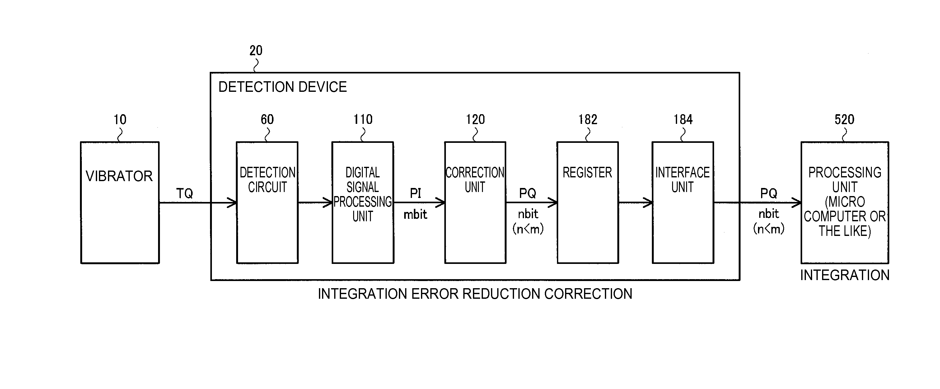
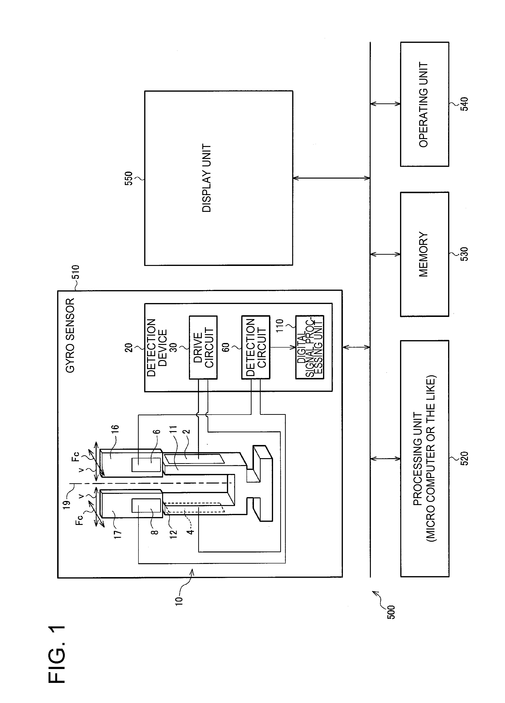
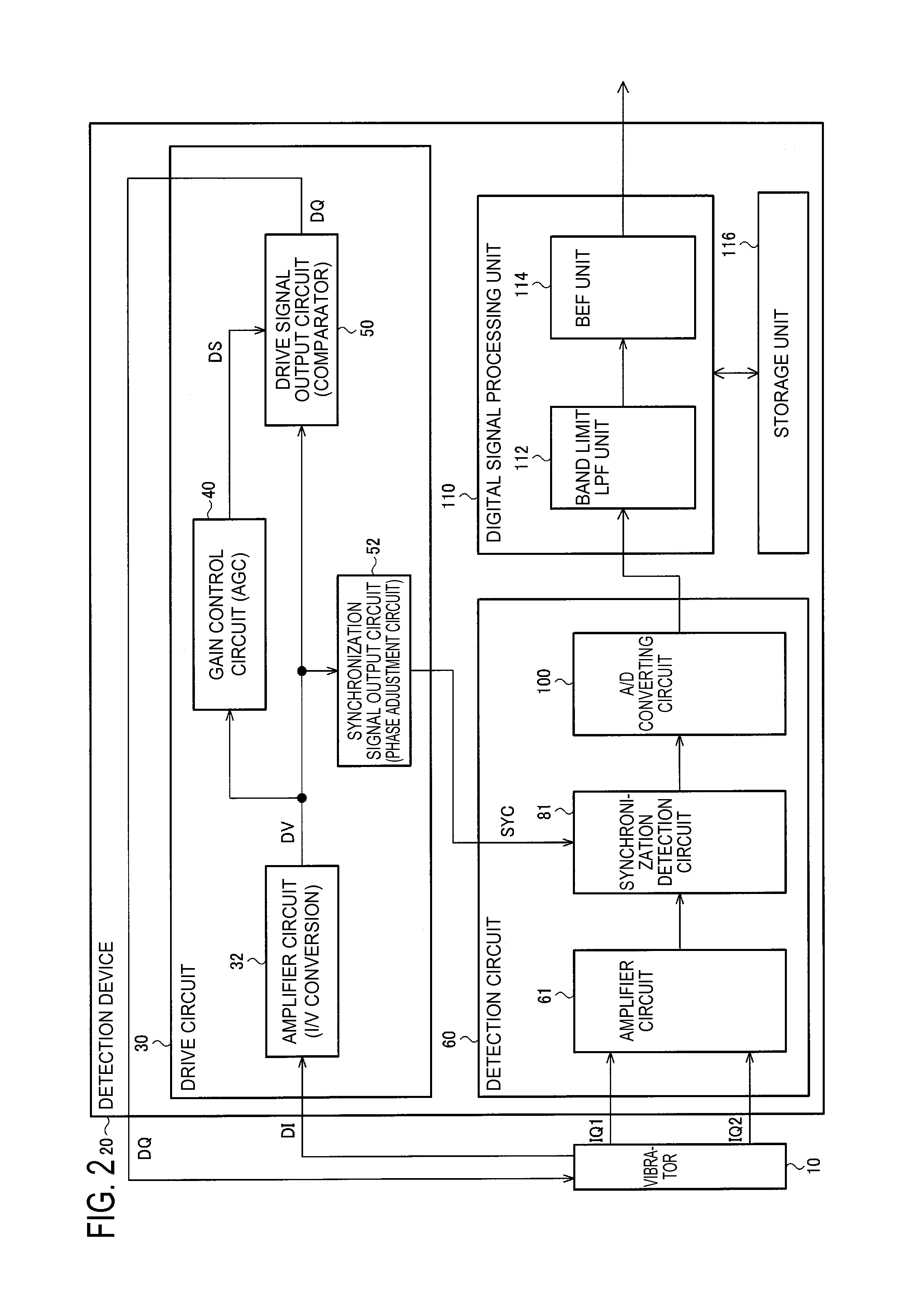
[0053]FIG. 1 shows a configuration example of a gyro sensor 510 (sensor in a broad sense) that includes a detection device o...


PUM


Abstract

A detection device includes: a drive circuit that receives a feedback signal from a vibrator and drives the vibrator; a detection circuit that performs detection based on a signal from the vibrator and outputs detection data; and a digital signal processing unit that performs digital filtering for the detection data from the detection circuit. The digital signal processing unit performs band elimination filtering for attenuating a component of a detuning frequency Δf=|fd−fs| corresponding to a difference between a drive side resonance frequency fd and a detection side resonance frequency fs of the vibrator for the detection data.

Description

BACKGROUND[0001]1. Technical Field[0002]The present invention relates to a detection device, a sensor, an electronic apparatus, a moving object and the like.[0003]2. Related Art[0004]A gyro sensor for detecting a physical quantity that changes due to external factors is assembled in an electronic apparatus such as a digital camera or a smart phone, or a moving object such as a vehicle or an airplane. The gyro sensor detects a physical quantity such as an angular velocity, and is used for image stabilization, posture control, GPS autonomous navigation or the like.[0005]For example, a vibration gyro sensor such as a quartz crystal piezoelectric vibration gyro sensor is known as one of the gyro sensors. In the vibration gyro sensor, a physical quantity corresponding to a Coriolis force generated by rotation is detected.[0006]In such a vibration gyro sensor, an unnecessary signal of a detuning frequency due to mechanical vibration such as a disturbance is generated. As a related art tec...

Claims


Application Information

Patent Timeline
Patent Type & Authority Applications(United States)
IPC IPC(8): G01C19/5776
CPCG01C19/5776G01C19/00G01C19/56G01C19/5712G01C19/5719G01C19/5726
Inventor NAKAJIMA, KATSUHITOMAKI, KATSUHIKO
Owner SEIKO EPSON CORP
Why Eureka
Try Eureka