Light control apparatus for an image sensing optical device

a technology of image sensing and control apparatus, which is applied in the direction of color television details, television systems, instruments, etc., can solve the problems of difficult to get difficult to precisely produce the miniaturized diaphragm blades, and difficult to achieve clear images in both dark and bright scenes. , to achieve the effect of reducing the size of the diaphragm

Inactive Publication Date: 2015-06-11
SODY
View PDF17 Cites 14 Cited by
  • Summary
  • Abstract
  • Description
  • Claims
  • Application Information

AI Technical Summary

Benefits of technology

[0023]The object of the present invention is to provide a method of reducing the size of a diaphragm to miniaturize an image sensing optical system in an image sensing device.

Problems solved by technology

To miniaturize the size of the IRIS system while retaining the performance of the system presents technical difficulties.
Therefore, it is difficult to get clear images in both dark and bright scenes by using miniaturized IRIS system.
Consequently, it is not easy to precisely produce the miniaturized diaphragm blades and but also to minimize the IRIS system using the diaphragm blades.
However, those methods present problems that, due to the polarizers attached on the LCD panel, the light transmittance of the LCD shutter at clear state is too low to get clear images in dark circumstances, and if the polarized light is incident on the image sensing device, the image quality may be compromised.
However, the method has problems including the loss in light transmittance due to a polarizing plate applied to the LCD, the transformation of an image attributable to the strong interaction between incident light and the polarizing plate, and difficulties in maintaining uniform light transmittance of the diaphragm due to the optical non-uniformity of electrode patterns that are formed to drive a plurality of pixels of the LCD.
Therefore, the method has not been put to practical use.

Method used


Image

  • Light control apparatus for an image sensing optical device
  • Light control apparatus for an image sensing optical device
  • Light control apparatus for an image sensing optical device

Examples


Embodiment Construction

[0056]Hereinafter, exemplary embodiments of the present invention will be described in detail. However, the present invention is not limited to the exemplary embodiments disclosed below, but can be implemented in various forms. The following exemplary embodiments are described in order to enable those of ordinary skill in the art to embody and practice the invention. The same reference numbers will be used throughout the drawings to refer to the same or similar parts, and redundant details will be omitted to make the descriptions clear.

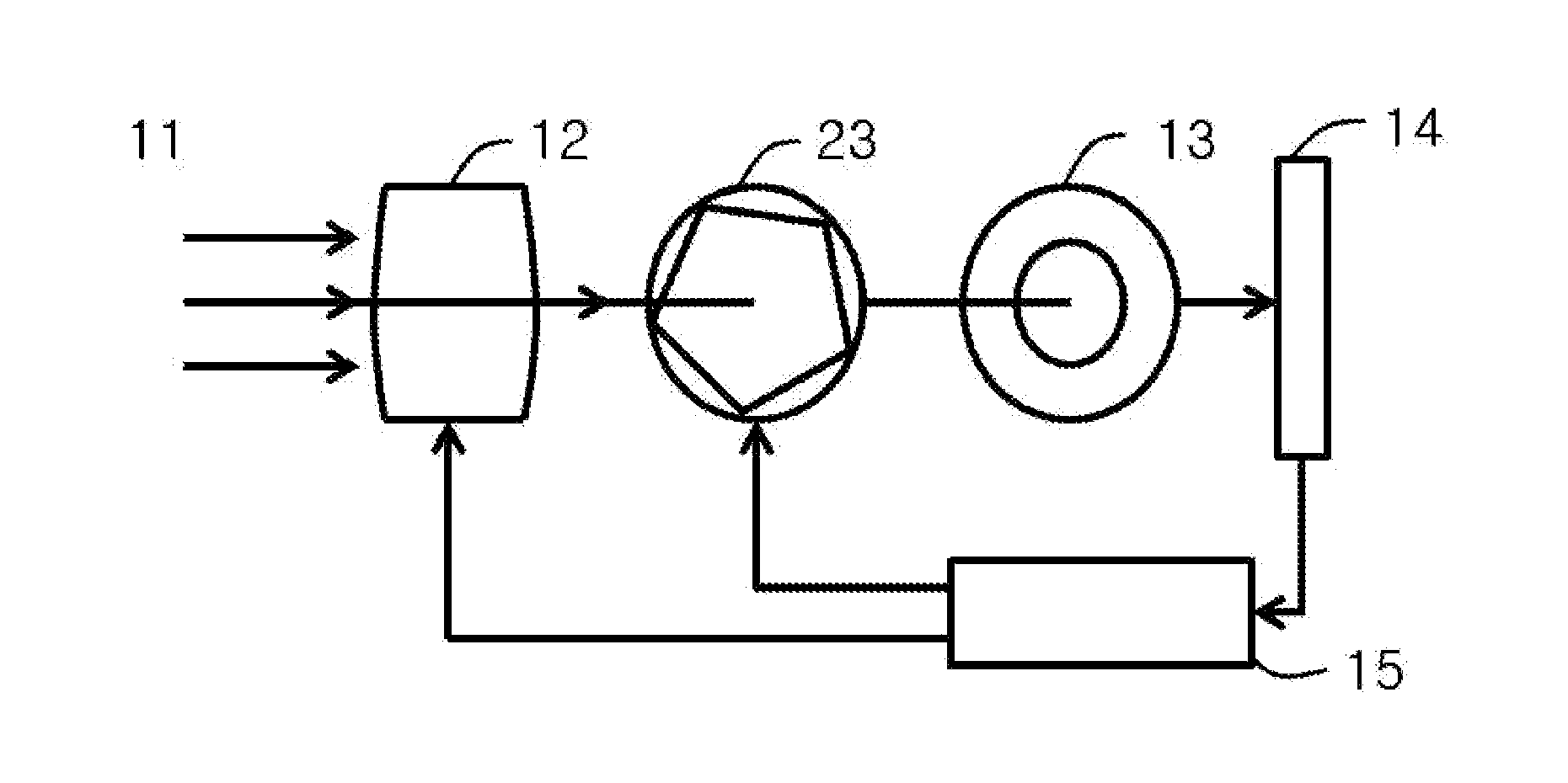
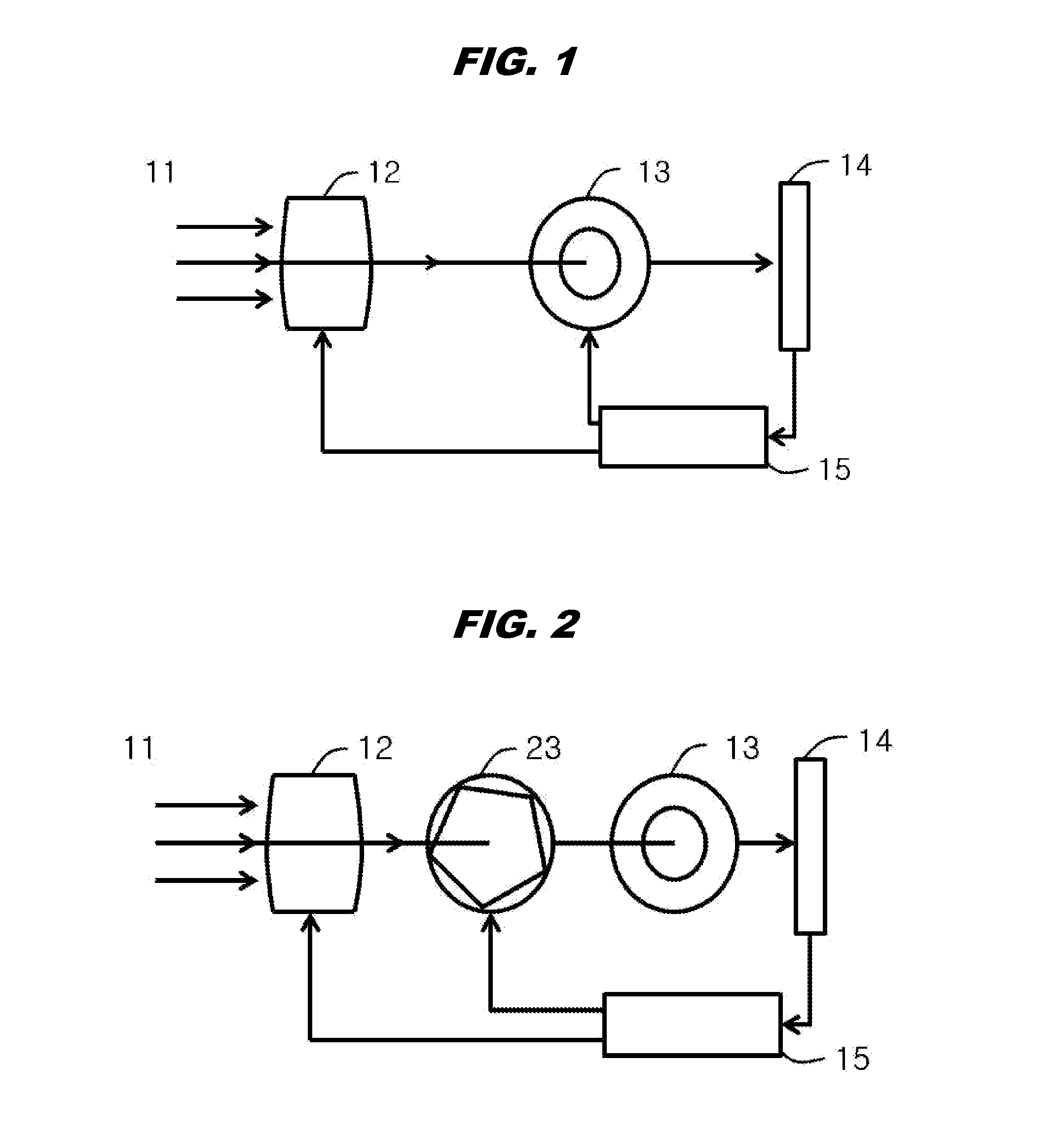
[0057]FIG. 1 is a simplified block diagram of an image sensing device applying a light control apparatus according to an embodiment of the present invention. The image sensing device includes a lens unit 12 which external incident light 11 travels through; and a light control apparatus disposed on the path of the incident light that has traveled through the lens unit 12, for controlling the amount of light admitted into a image sensor 14.

[0058]The lig...


PUM

PropertyMeasurementUnit
visible light transmittanceaaaaaaaaaa
voltageaaaaaaaaaa
sizeaaaaaaaaaa

Abstract

An apparatus for controlling the quantity of light incident on an image sensor by controlling size or shape of a diaphragm and also by adjusting light transmittance of the diaphragm is provided. The light control apparatus is disposed on the light path of the image sensing device and controls a quantity of light incident on the image sensor. The light control apparatus includes a Guest-Host LCD panel applied no polarizing film and a control unit for reducing the time to take multi-frame detection by driving voltages which are applied to respective pixels of the Guest-Host LCD panel, to be increased at least when taking multiple frames in series. The Guest-Host LCD panel has a plurality of pixels forming closed curves or boundaries on a plane, which are electrically driven individually. Also, the pixels have uniform light transmittance throughout the entire azimuth of the closed curves or boundaries with an origin.

Description

BACKGROUND OF THE INVENTION[0001]1. Field of the Invention[0002]The present invention relates generally to a light control apparatus for an image sensing device and, more particularly, to an apparatus for controlling an amount of light incident on an image sensing device by adjusting size of a diaphragm or light transmittance of the diaphragm.[0003]2. Description of the Related Art[0004]There have been recent demands for miniaturization and high performance of image sensing devices such as digital video cameras, digital still cameras, and smart-phones. To meet such demands, in other words, to make the image sensing device smaller, a miniaturized and high-density integrated CCD (Charge Coupled Device) or a high-density CMOS (Complementary Metal-Oxide Semiconductor) chip is used as the image sensing tool.[0005]Also, to miniaturize the size of the image sensing device, it is necessary to reduce the size of both lens and diaphragm. The usual optic diaphragm applied to a general image se...

Claims


Application Information

Patent Timeline
Patent Type & Authority Applications(United States)
IPC IPC(8): H04N5/238G02F1/133
CPCG02F1/13306H04N5/238G02F1/134309G02F1/13725H04N23/75
Inventor LEE, JONG-CHEON
Owner SODY
Why Eureka
Try Eureka