Control device for hybrid vehicle

a control device and hybrid technology, applied in the direction of vehicle position/course/altitude control, process and machine control, instruments, etc., can solve the problems of engine not being controlled appropriately, engine air-fuel ratio may continue to be lean, air-fuel ratio sensor, etc., to prevent unnecessary exercise of catalyst protective control, reduce fuel remaining amount, and prevent damage to exhaust purification catalyst due to the rise in exhaust temperature

Active Publication Date: 2015-06-18
MITSUBISHI MOTORS CORP
View PDF28 Cites 2 Cited by
  • Summary
  • Abstract
  • Description
  • Claims
  • Application Information

AI Technical Summary

Benefits of technology

[0021]According to the present invention, as described above, catalyst protective control is exercised with an appropriate timing, whereby a rise in the exhaust temperature associated with a decrease in the fuel remaining amount can be suppressed. Eventually, damage to the exhaust purification catalyst due to the rise in the temperature of exhaust can be prevented. Moreover, unnecessary exercise of catalyst protective control can be prevented to suppress deterioration of drivability.

Problems solved by technology

However, if the amount of fuel remaining in a fuel tank is small, for example, fuel supply may be insufficient, and the exhaust air-fuel ratio may continue to be lean.
If such a lean state of the exhaust air-fuel ratio persists, there is a possibility that the exhaust air-fuel ratio sensor will be erroneously judged to be abnormal, and the engine cannot be controlled appropriately.

Method used


Image

  • Control device for hybrid vehicle
  • Control device for hybrid vehicle
  • Control device for hybrid vehicle

Examples


embodiment 1

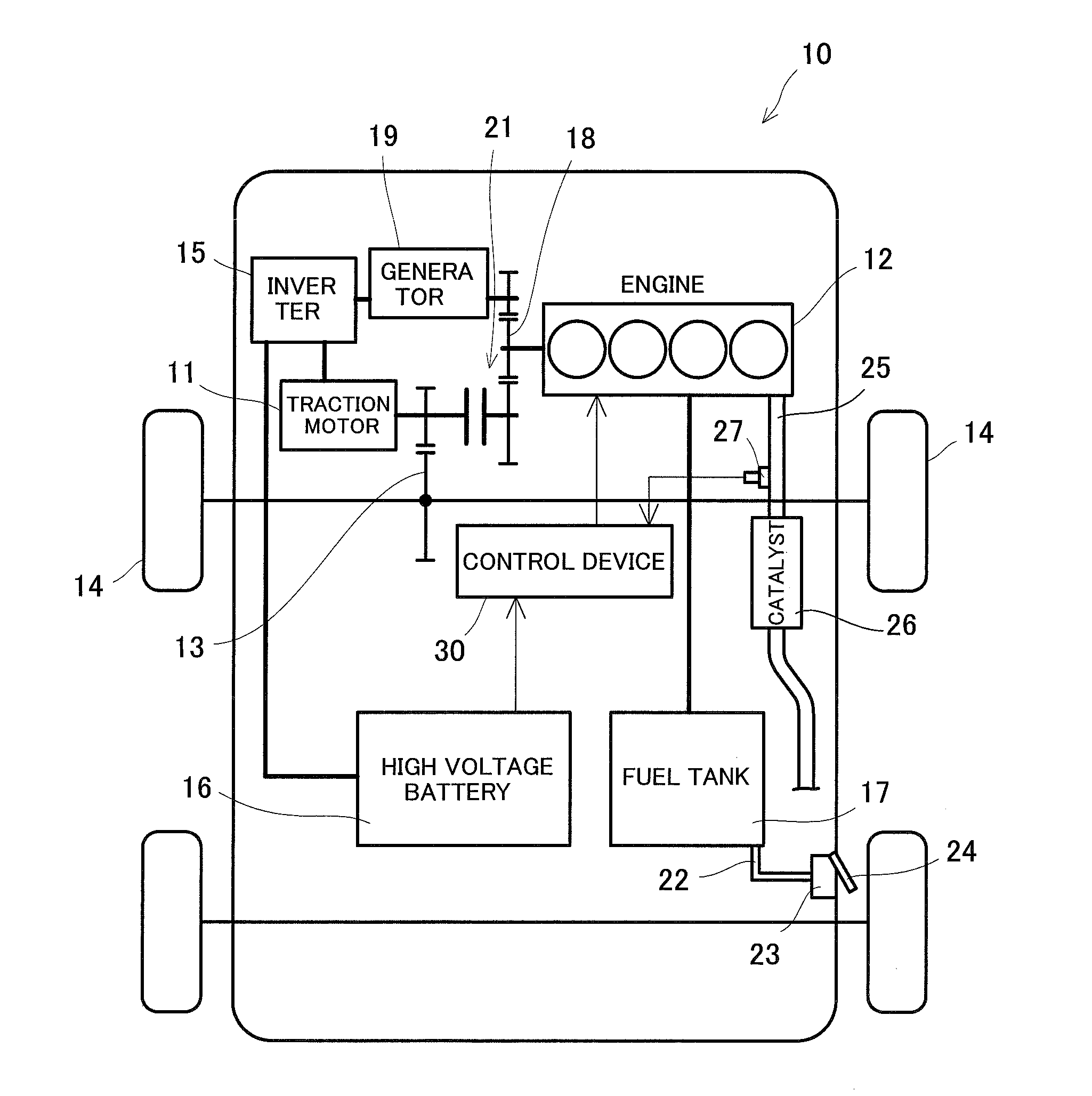
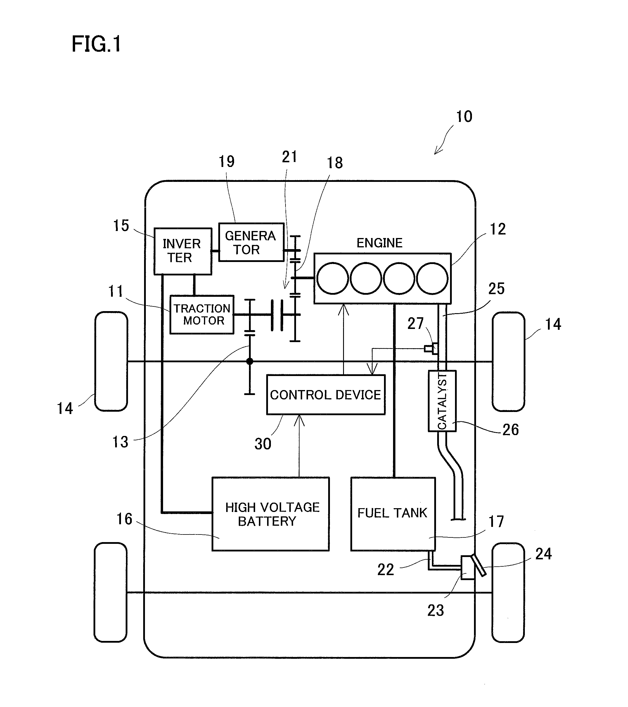
[0028]As shown in FIG. 1, a hybrid vehicle (may hereinafter be referred to simply as “vehicle”) 10 according to the present embodiment has, as a drive source for traveling, a traction motor 11 and an engine 12. The traction motor 11 is connected to front wheels 14 via a power transmission mechanism 13. A high voltage battery 16 is connected to the traction motor 11 via an inverter (motor inverter) 15.

[0029]The engine 12 is driven by combustion of fuel supplied from a fuel tank 17. The engine 12 is connected to a generator (electric power generator) 19 via an output system 18. The generator 19 is connected to the high voltage battery 16 via the inverter (generator inverter) 15. The output system 18 is connected to the generator 19 on one hand, and is also connected to the power transmission mechanism 13 via a clutch 21 on the other hand.

[0030]The fuel tank 17 is connected via a fuel pipe 22 to an oil filler port 23 provided in a vehicle body, and fuel is supplied through the oil fill...

embodiment 2

[0046]FIG. 4 is a block diagram of a control device for a hybrid vehicle according to Embodiment 2 of the present invention.

[0047]The present embodiment is an example in which a timing for exercising catalyst protective control is adjusted according to the combustion state of the engine 12 at the time of staring the engine 12. Concretely, it is an example in which after a lapse of a second predetermined time from detection of the complete explosion of the engine 12 at the time of starting the engine 12, determination by a determination unit 32 is made, and catalyst protective control is exercised based on the results of determination.

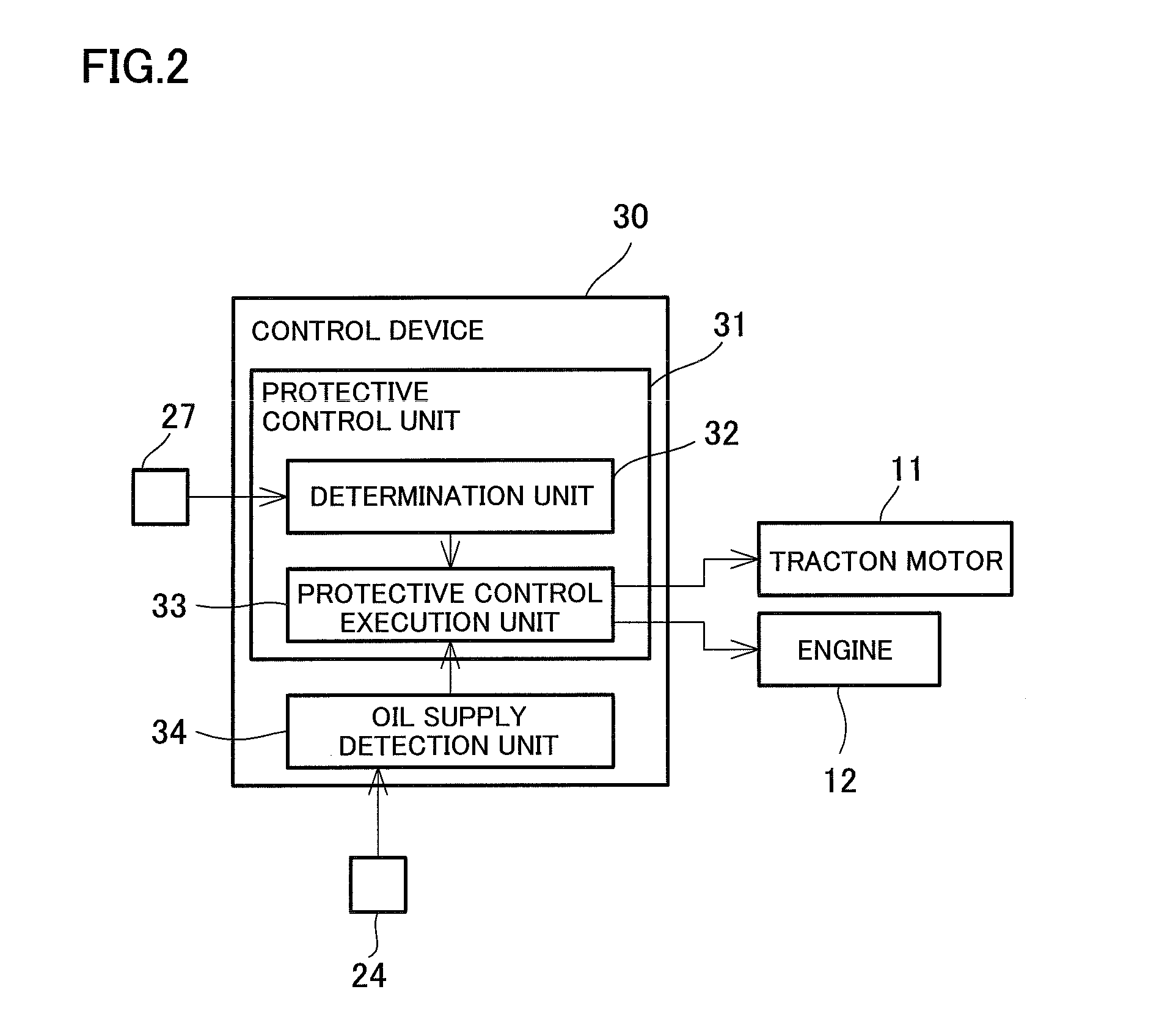
[0048]As shown in FIG. 4, a control device 30 according to the present embodiment further includes a complete explosion detection unit 35 in addition to the determination unit 32 and a protective control execution unit 33, which constitute a protective control unit 31, and an oil supply detection unit 34.

[0049]The complete explosion detection unit 35 de...


PUM


Abstract

A control device for a hybrid vehicle, which can inhibit damage to an exhaust purification catalyst and also suppress deterioration of drivability, is provided. The control device exercises catalyst protective control, which inhibits operation of an engine and drives a traction motor, if a state where an exhaust air-fuel ratio detected by an exhaust air-fuel ratio detection unit is lean continues for a first predetermined time or longer.

Description

[0001]The entire disclosure of Japanese Patent Application No. 2013-258637 filed Dec. 13, 2013 is expressly incorporated by reference herein.TECHNICAL FIELD[0002]This invention relates to a control device for a hybrid vehicle equipped with an engine (internal combustion engine) and a traction motor (electric motor) as a drive source.BACKGROUND ART[0003]An engine loaded on a vehicle is generally subjected to feedback control so that the air-fuel ratio of exhaust becomes a target air-fuel ratio, based on the results of detection by an exhaust air-fuel ratio sensor (for example, an O2 sensor or a linear air-fuel ratio sensor (LAFS)) provided in an exhaust pipe.[0004]However, if the amount of fuel remaining in a fuel tank is small, for example, fuel supply may be insufficient, and the exhaust air-fuel ratio may continue to be lean. If such a lean state of the exhaust air-fuel ratio persists, there is a possibility that the exhaust air-fuel ratio sensor will be erroneously judged to be a...

Claims


Application Information

Patent Timeline
Patent Type & Authority Applications(United States)
IPC IPC(8): B60W20/00B60W10/08B60W10/30B60W10/06B60L50/16
CPCB60W20/50B60W10/06Y10S903/93B60W10/30B60W10/08B60K6/442B60W2050/0295B60W2510/0619B60W2530/209Y02T10/62Y02T10/7072
Inventor UENO, HIROAKIMIYATA, TOSHIYUKI
Owner MITSUBISHI MOTORS CORP
Why Eureka
Try Eureka