
Motor

a technology of permanent magnets and motors, which is applied in the direction of rotating magnets, magnetic circuit rotating parts, synchronous machines with stationary armatures, etc., can solve the problems of weakening the strength of the magnetic field produced by the permanent magnet, weakening the magnetic field strength of the permanent magn

Active Publication Date: 2015-06-18
SAMSUNG ELECTRONICS CO LTD
View PDF3 Cites 16 Cited by
  • Summary
  • Abstract
  • Description
  • Claims
  • Application Information

AI Technical Summary

Benefits of technology

The present patent provides a motor with a stator and rotor that have features to attenuate a magnetic field that causes demagnetization. This includes the use of stator magnetic barriers on the teeth close to the rotor, which interrupt magnetic flux. The stator magnetic barriers may be made of non-magnetic material or air, and may be positioned at different locations on the teeth. The rotor may also include a plurality of pole modules and a magnetic member to concentrate the magnetic field, with permanent magnets embedded in the pole modules. The motor may also have a plurality of permanent magnet groups with different magnetization directions. The technical effect of this design is to improve the performance and stability of motors by reducing demagnetization, which can lead to decreased efficiency and durability.

Problems solved by technology

In other words, the magnetic field produced by the coil may magnetize the permanent magnet in the opposite direction, or may weaken the magnetic field strength of the permanent magnet.
In addition, when demagnetization of the permanent magnet occurs, the strength of the magnetic field produced by the permanent magnet is weakened.

Method used


Image

  • Motor
  • Motor
  • Motor

Examples


Embodiment Construction

[0043]Reference will now be made in detail to the embodiments of the present disclosure, examples of which are illustrated in the accompanying drawings, wherein like reference numerals refer to like elements throughout.

[0044]It should be understood that embodiments disclosed in this specification and constituents shown in the accompanying drawings are simply illustrative and there may be many variations which may replace the embodiments and drawings of this specification at the time of filing of this application.

[0045]Reference will now be made in detail to the embodiments of the present disclosure, examples of which are illustrated in the accompanying drawings, wherein like reference numerals refer to like elements throughout.

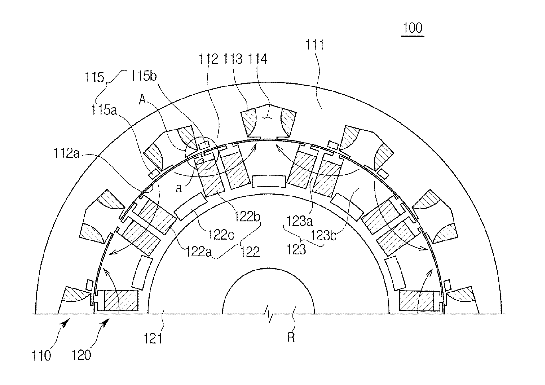
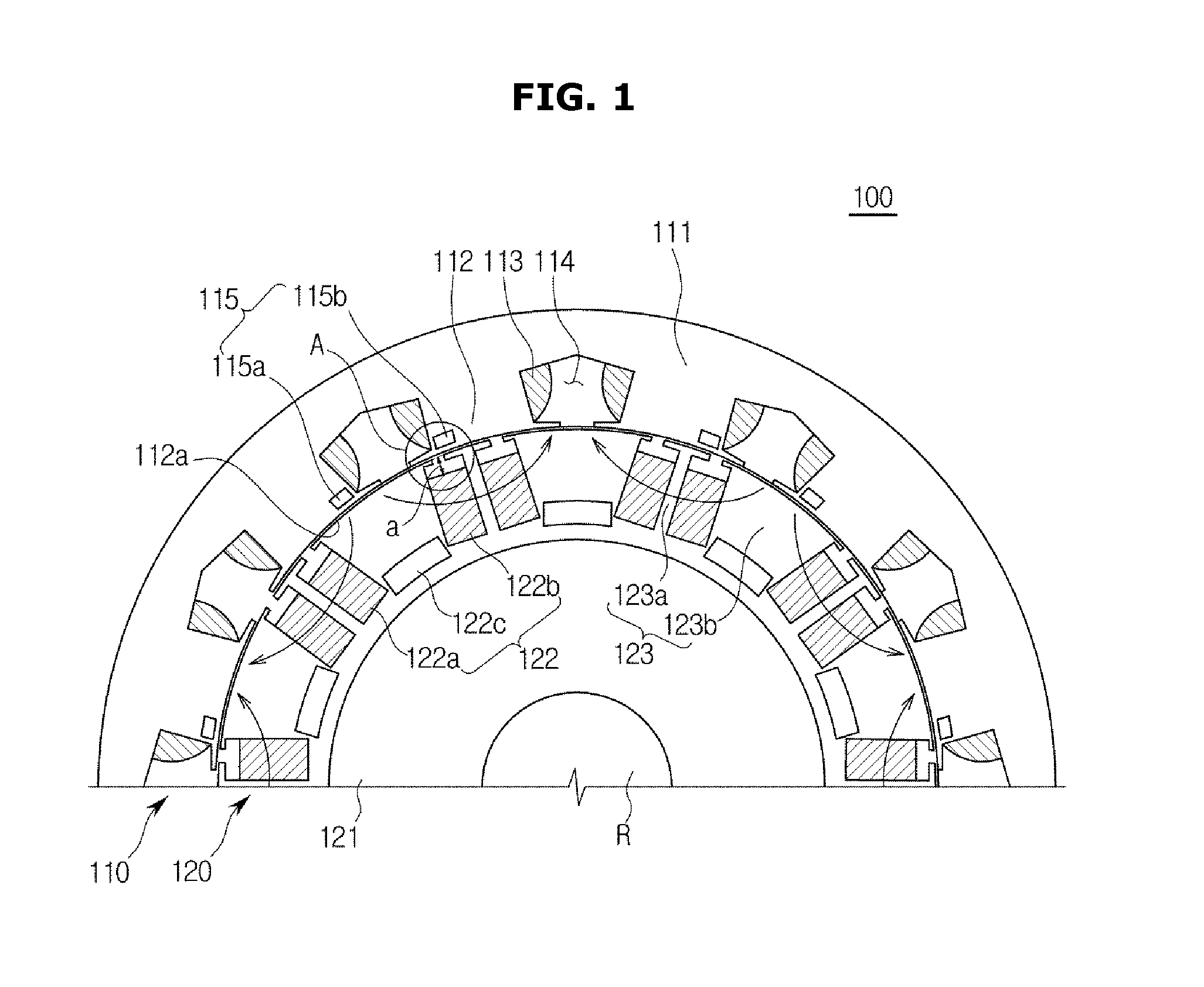
[0046]FIG. 1 is a cross-sectional view illustrating a motor according to an exemplary embodiment of the present disclosure.

[0047]As shown in FIG. 1, a motor 100 according to one embodiment includes a stator 110 fixed by an external support structure (not shown...


PUM


Abstract

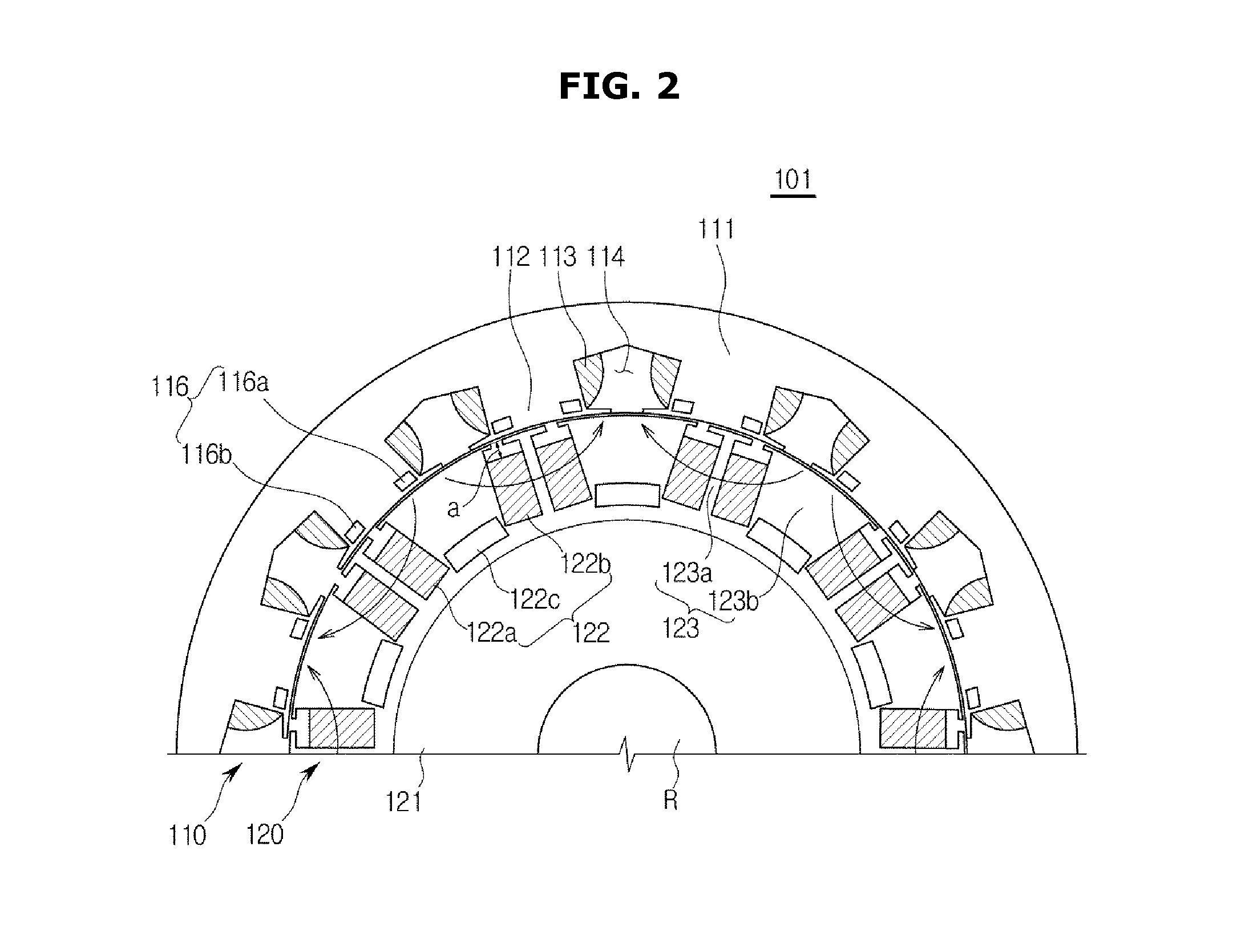
A motor including a stator, and a rotor adapted to rotate, wherein the stator includes a stator body, a plurality of teeth protruding from the stator body toward the rotor, and at least one stator magnetic barrier provided to each of the teeth to interrupt magnetic flux. A magnetic field produced in a direction parallel to the outer circumferential surface of the rotor is attenuated, and therefore demagnetization of permanent magnets included in the rotor may be prevented.

Description

CROSS-REFERENCE TO RELATED APPLICATION[0001]This application claims the benefit of Korean Patent Application No. 10-2013-0154505, filed on Dec. 12, 2013 in the Korean Intellectual Property Office, the disclosure of which is incorporated herein by reference.BACKGROUND[0002]1. Field[0003]Embodiments of the present disclosure relate to an interior permanent magnet (IPM) motor having a permanent magnet provided in the rotor.[0004]2. Description of the Related Art[0005]Motors are widely used in home appliances including a laundry machine, a refrigerator, an air conditioner, and a cleaner. They are used even in electric vehicles and hybrid vehicles, which have recently attracted attention.[0006]Among the motors, a permanent magnet motor employing a permanent magnet rotates a rotor using magnetic interaction between a magnetic field produced by a coil through which electrical current flows and a magnetic field produced by the permanent magnet.[0007]The permanent magnet may be demagnetized ...

Claims


Application Information

Patent Timeline
IPC IPC(8): H02K1/27H02K1/14
CPCH02K1/146H02K1/2773H02K21/16H02K1/06H02K1/27H02K21/02H02K21/12
Inventor KIM, SUNG ILKIM, SEONG TAEK
Owner SAMSUNG ELECTRONICS CO LTD
Learn More