
Multisensory detector

a detector and multi-sensor technology, applied in the field of microelectronics industry, can solve the problems of limiting the size of the mems component, the production of pads may be a limiting factor, and the size of the components is larger, so as to reduce the number of pads present, the effect of reducing energy consumption

Active Publication Date: 2015-06-25
COMMISSARIAT A LENERGIE ATOMIQUE ET AUX ENERGIES ALTERNATIVES
View PDF17 Cites 2 Cited by
  • Summary
  • Abstract
  • Description
  • Claims
  • Application Information

AI Technical Summary

Benefits of technology

The invention describes a way to reduce energy consumption in a wireless network by using multiple branches that share a common source. This also reduces the number of pads needed for measuring impedance variations. The branches are connected on a substrate using a system like MEMS or NEMS. The technical effects are improved efficiency and reduced cost.

Problems solved by technology

As a matter of fact, this would lead to a size of components larger than the space required for positioning the MEMS structures, and thus entail a much too high cost of production.
The production of the pads may thus be a limiting factor for reducing the size of the MEMS component.

Method used


Image

  • Multisensory detector
  • Multisensory detector
  • Multisensory detector

Examples


Embodiment Construction

[0023]Before making a detailed review of the embodiments of the invention, optional characteristics which may be used in combination or as alternative solutions are listed hereafter:

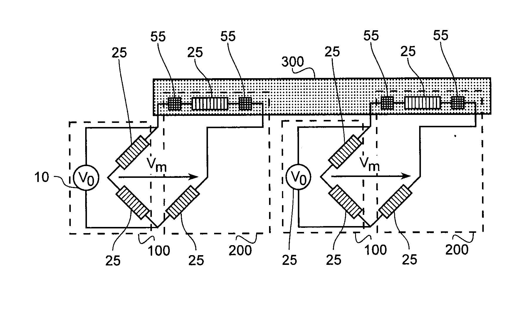
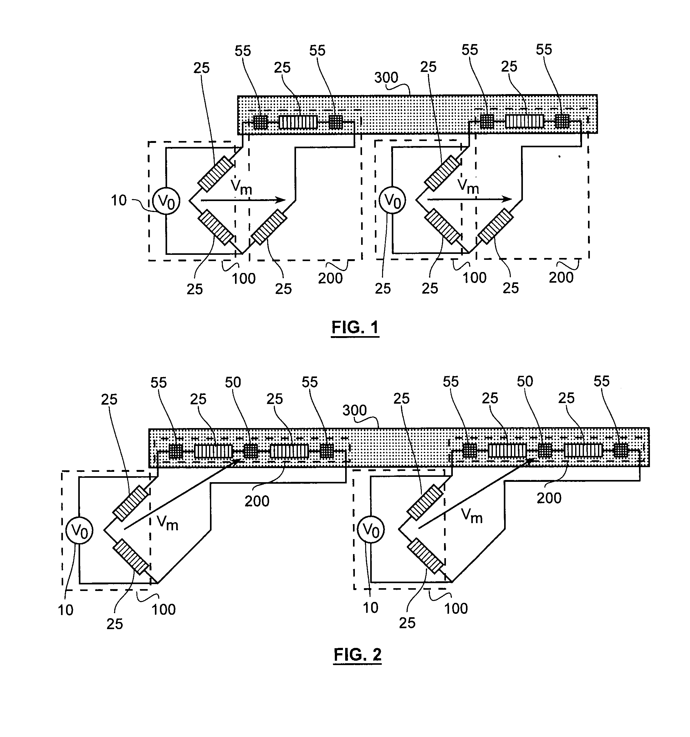
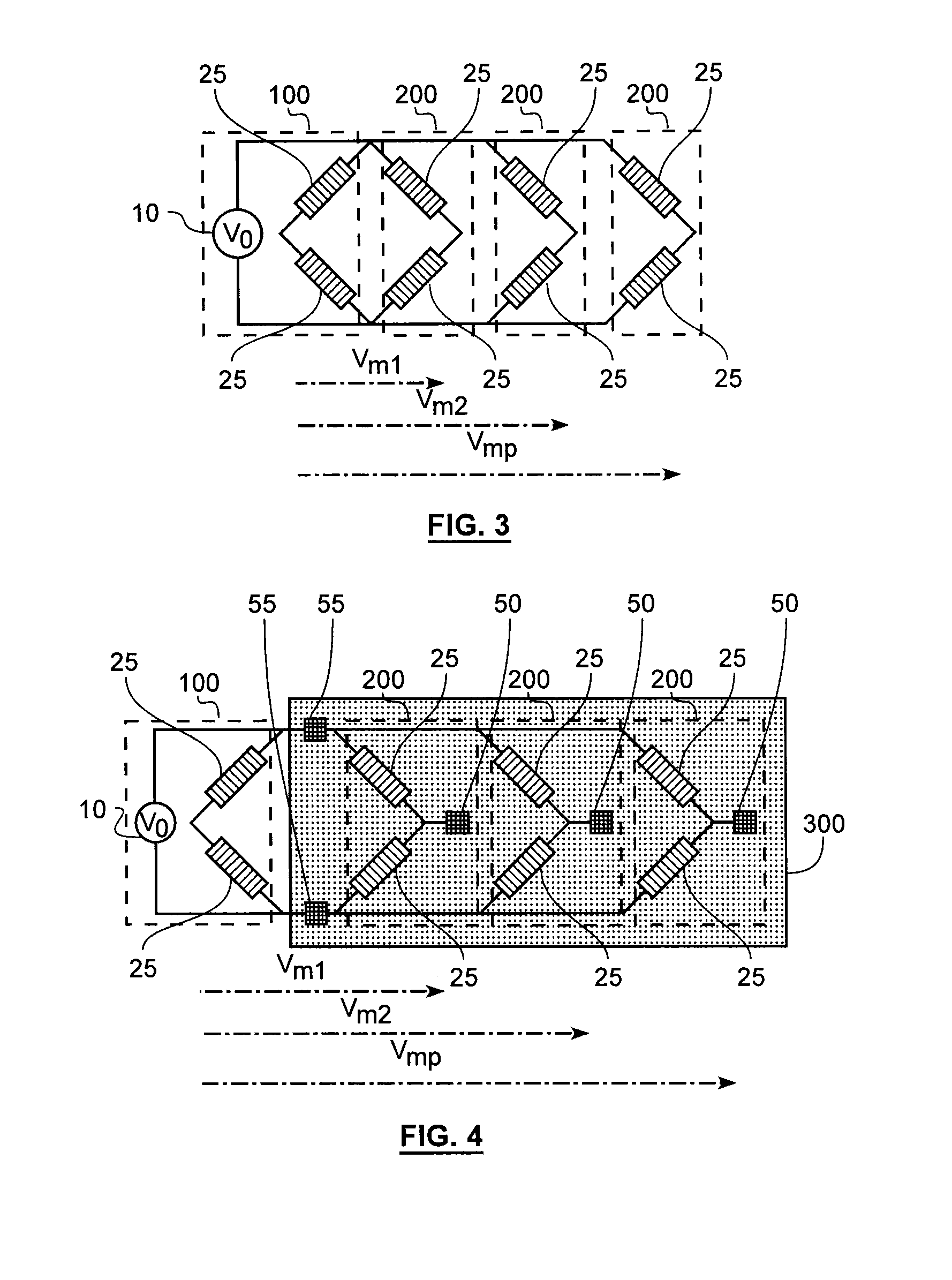
[0024]Advantageously, the circuit comprises at least one dipole having a variable impedance according to the evolution of a measurand in at least one detection branch.

[0025]The reference branch is connected to the detection branches, either directly, or using a first pad and a second polarizing pad.

[0026]Each detection branch is particularly advantageously connected to at least one central measuring pad located between the dipoles of said detection branch, at the mid-point of the detection branches.

[0027]Two additional measuring pads are preferably mounted in parallel and so configured as to control the polarizing voltage of the detection branches.

[0028]The multisensory detector particularly advantageously comprises at least the measuring circuit.

[0029]Advantageously, the measuring circuit is partially f...


PUM


Abstract

The invention relates to a measuring circuit for a multisensory detector characterized in that it comprises:a plurality of detection branches mounted in parallel, with each one comprising at least two dipoles mounted in series,and, at least one reference branch, comprising a polarizing source and at least two dipoles mounted in series; with said reference branch being connected in parallel to at least two detection branches among the plurality of branches, so as to form a Wheatstone bridge with each one of the detection branches among the plurality of detection branches.

Description

FIELD OF THE INVENTION[0001]The present invention relates to the microelectronics industry, which covers the microelectronics as well as the nanoelectronics techniques. More particularly, the invention relates to a multisensory detector for a microelectromechanical (<<MEMS>>) or a nanoelectromechanical (<<NEMS>>) system.TECHNOLOGICAL BACKGROUND[0002]The consumer market of the multi-sensory detectors such as 3-axis accelerometers, 3-axis magnetometers, 3-axis gyrometers and pressure detector types, is oriented towards always smaller sizes of components to reach a competitive cost.[0003]Thus, the size of a 9-axis detector, including a silicon chip of the microelectromechanical system (<<MEMS>>) type, the signal processing electronics comprising the integrated circuit specific to an application (the acronym <<ASIC>> for <<Application-Specific Integrated Circuit>>) and the package, currently has a dimension of 4×4 mm2 (mm=milli...

Claims


Application Information

Patent Timeline
IPC IPC(8): G01R17/10G01R19/00
CPCG01R19/0084G01R17/105G01R33/0206G01R33/038
Inventor JOURDAN, GUILLAUMEDIEM, BERNARDREY, PATRICEROBERT, PHILIPPE
Owner COMMISSARIAT A LENERGIE ATOMIQUE ET AUX ENERGIES ALTERNATIVES
Learn More