Apparatus and method for inspecting a surface of a sample

a surface inspection and apparatus technology, applied in the direction of material analysis using wave/particle radiation, instruments, nuclear engineering, etc., can solve the problems of deteriorating the imaging quality of the apparatus, and achieve the effects of reducing aberration, reducing aberration, and increasing the aberration of the non-immersion lens

Active Publication Date: 2015-06-25
TECH UNIV DELFT
View PDF8 Cites 16 Cited by
  • Summary
  • Abstract
  • Description
  • Claims
  • Application Information

AI Technical Summary

Benefits of technology

[0016]In an embodiment, the lens system comprises a magnetic objective lens. In an embodiment, the apparatus comprises a sample holder which is arranged for positioning the sample surface to be immersed in the magnetic field of the objective lens. Such an arrangement gives low aberrations for the primary electrons, which is an advantage in a microscope. Here an immersion arrangement is even more advantageous, because there must be space between the sample and a non-immersion lens to accelerate the electrons upwards, which would further increase the aberrations of the non-immersion lens. In an immersion lens the acceleration is inside the lens, which reduces aberrations. Also extracting the secondary electrons from the immersion field gives an additional possibility to set the magnification of the projection of the secondary electrons onto the secondary electron detector to a desired value.

Problems solved by technology

A disadvantage of this system is that the use of the beam splitter as described in U.S. Pat. No. 7,554,094 deteriorates the imaging quality of the apparatus.

Method used


Image

  • Apparatus and method for inspecting a surface of a sample
  • Apparatus and method for inspecting a surface of a sample
  • Apparatus and method for inspecting a surface of a sample

Examples


Embodiment Construction

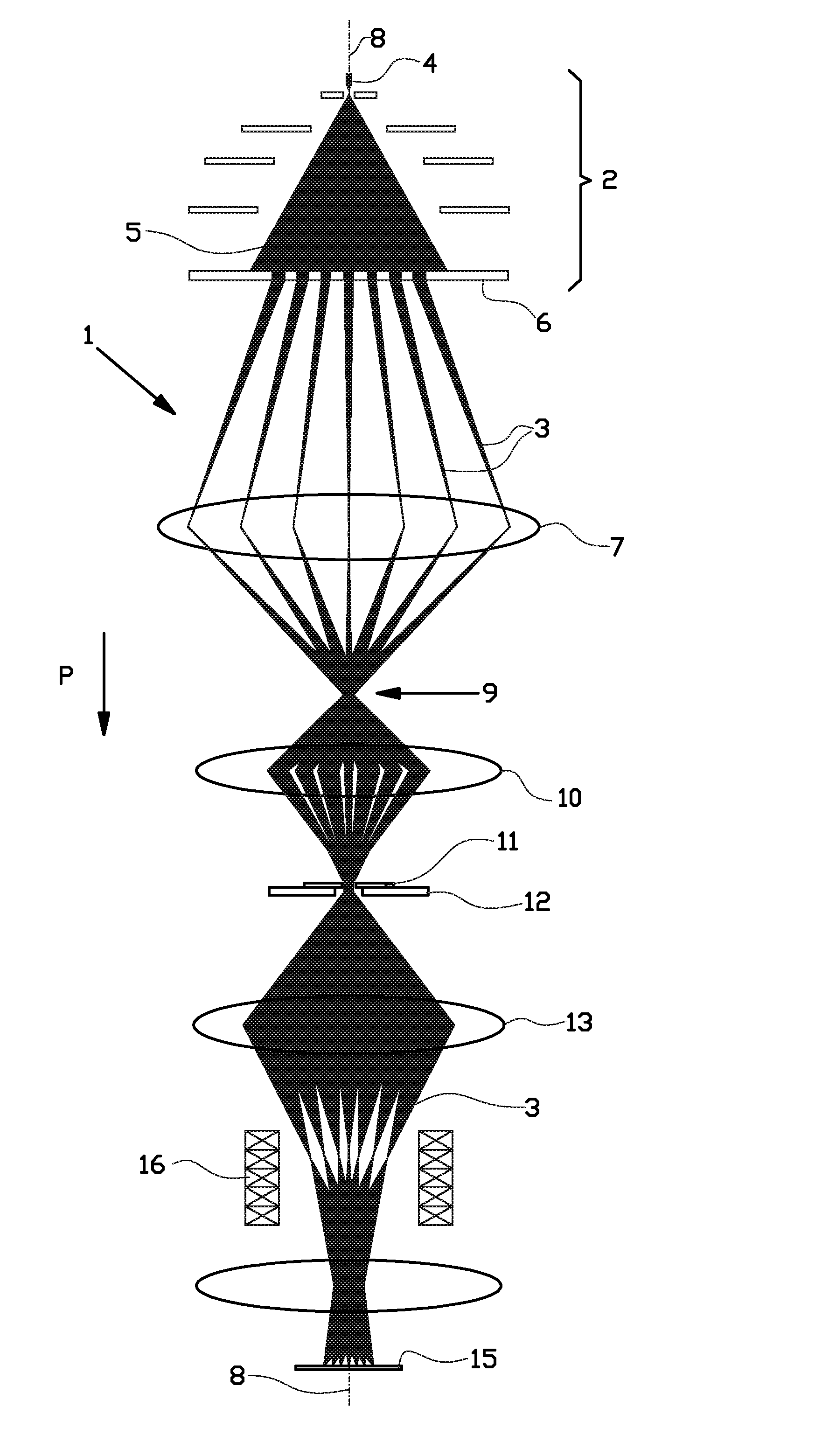
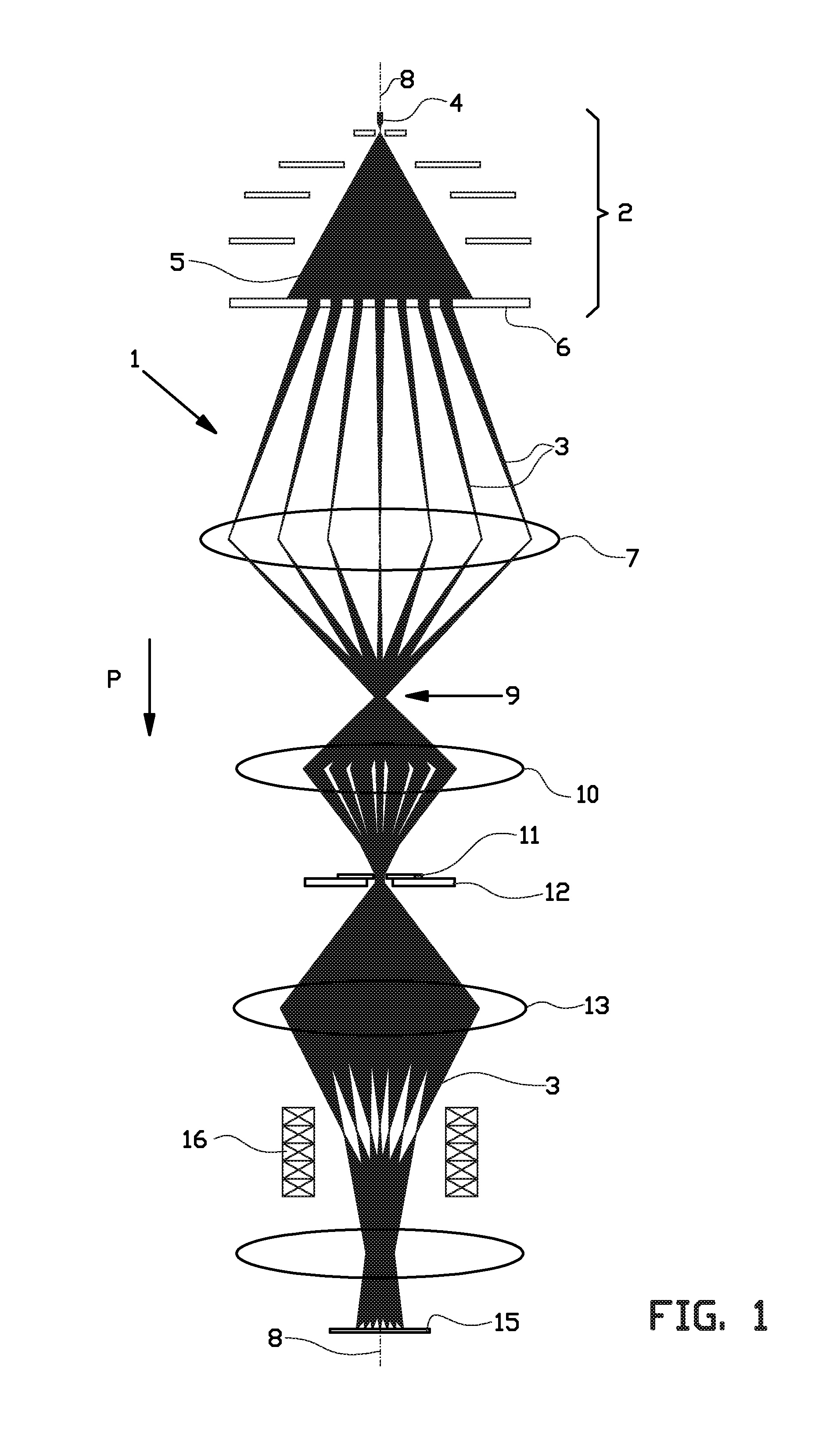
[0041]FIG. 1 shows an example of a Multi-Beam Scanning Electron Microscope (MBSEM) of the invention.

[0042]The MBSEM 1 comprises a multi beam charged particle generator 2 for generating an array of primary charged particle beams 3, in this case an array of primary electron beams 3. The multi beam electron generator 2 comprises at least one electron source 4 for generating a diverging electron beam 5. The diverging electron beam 5 is split into an array of focused primary electron beams 3 by an aperture lens array 6. The primary electron beams 3 are subsequently directed towards a sample 15, as schematically indicated by the arrow P.

[0043]The multiple images of the source 4 are positioned on the object principle plane of an accelerator lens 7. The accelerator lens 7 directs the primary electron beams 3 towards the optical axis 8 and creates a first common cross-over 9 of all the primary electron beams 3.

[0044]The first common cross-over 9 is imaged by the magnetic condenser lens 10 on...


PUM


Abstract

The invention relates to an apparatus for inspecting a surface of a sample, wherein the apparatus comprises: at least one charged particle source for generating an array of primary charged particle beams, a condenser lens for directing all charged particle beams to a common cross-over, a lens system for directing the primary charged particle beams from the common cross-over towards the sample surface and for focusing all primary charged particle beams into an array of individual spots on the sample surface, and a position sensitive secondary electron detector positioned at least substantially in or near a plane comprising said common cross-over.

Description

BACKGROUND[0001]The invention relates to an apparatus and a method for inspecting a surface of a sample. In particular the invention relates to an apparatus for inspecting a sample surface using a plurality of charged particle beams, such as a multi-beam scanning electron microscope. The invention may be applied to charged particles of any type, such as electrons, positrons, ions and others.[0002]Such an apparatus is for example disclosed in U.S. Pat. No. 7,554,094. This US patent discloses an electron microscope comprising a charged particle source for generating an array of primary electron beams. These primary electron beams pass a field lens. Downstream of this field lens, the primary electron beam path is a converging beam path having a cross-over in an intermediate plane upstream of an objective lens. The objective lens directs the primary charged particle beams from the common cross-over towards the sample surface and focuses the primary charged particle beams into an array o...

Claims


Application Information

Patent Timeline
Patent Type & Authority Applications(United States)
IPC IPC(8): H01J37/244H01J37/14H01J37/28
CPCH01J37/244H01J37/14H01J37/28H01J2237/2446H01J37/21H01J2237/2448
Inventor KRUIT, PIETERGHEIDARI, ALI MOHAMMADIREN, YAN
Owner TECH UNIV DELFT
Why Eureka
Try Eureka