DC power supply device, and control method for DC power supply device

a power supply device and control method technology, applied in the direction of process and machine control, spark gap circuit, instruments, etc., can solve the problems of increasing the impact of load, affecting the operation, and prolonging the arcing time, so as to reduce the delay in supplying dc power, suppress output voltage fluctuations, and reduce the effect of a delay

Active Publication Date: 2015-06-25
KYOSAN ELECTRIC MFG CO LTD
View PDF5 Cites 19 Cited by
  • Summary
  • Abstract
  • Description
  • Claims
  • Application Information

AI Technical Summary

Benefits of technology

[0055]As discussed above, according to the present invention, it is possible in restarting the inverter, to synchronize the phase of the pulse control signal upon restarting, with the phase of the pulse control signal upon suspending, in the DC power supply device provided with the inverter.
[0056]In addition, according to the present invention, the phase of the pulse control signal upon restartin...

Problems solved by technology

A voltage type direct power source has problems as the following; a large capacitor which is connected to output may cause a flow of excessive discharge current at the time of arc occurrence, and the output power is further increased in order to compensate for reduction of output voltage upon arc occurrence, thereby elongating the arcing time and resulting in increase of impact on the load.
Since it is difficult to perform the startup operation and the stop operation at high speed, this may lead to unstable operations.
On the other hand, in an a...

Method used


Image

  • DC power supply device, and control method for DC power supply device
  • DC power supply device, and control method for DC power supply device
  • DC power supply device, and control method for DC power supply device

Examples


Embodiment Construction

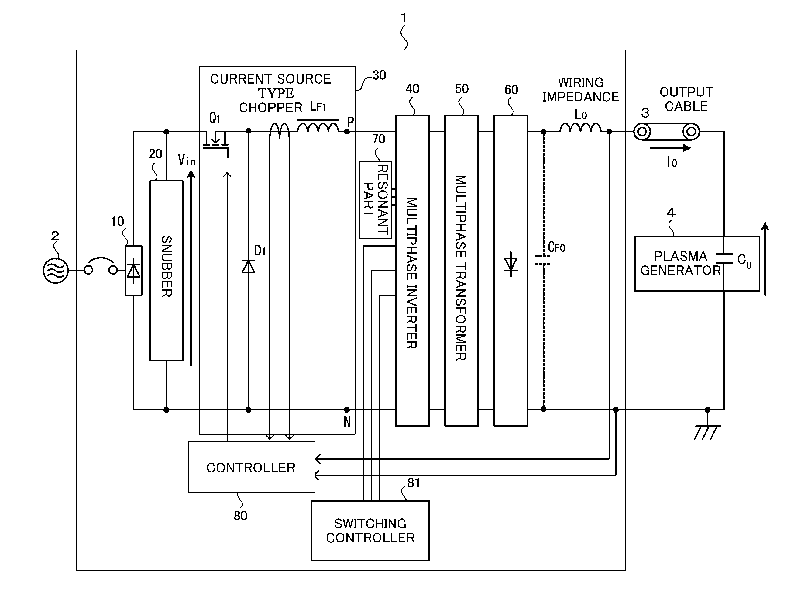
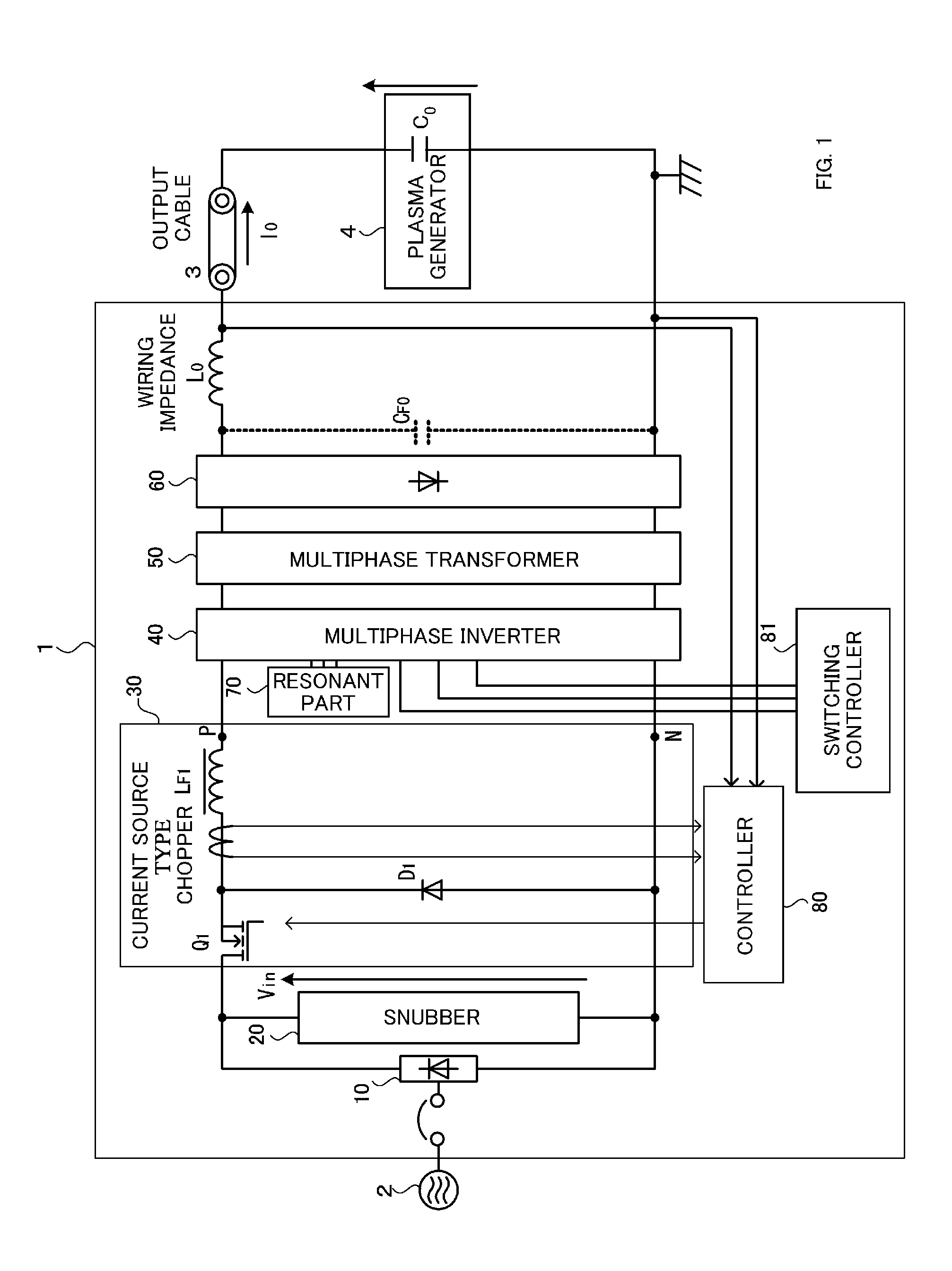
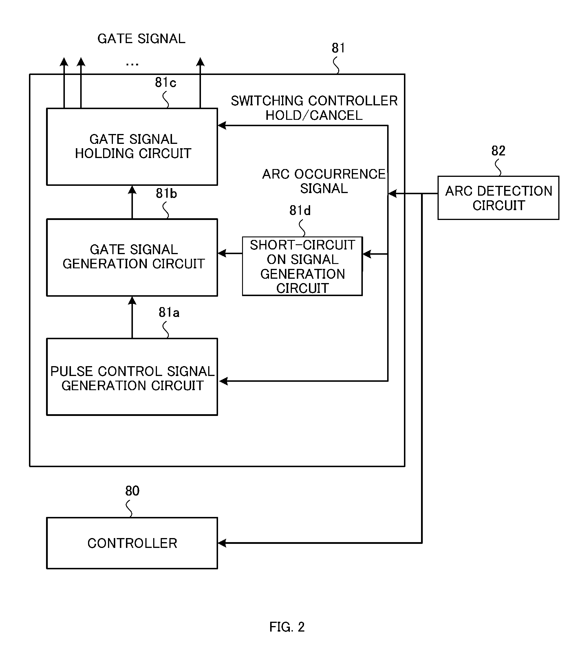
[0065]Hereinafter, embodiments of the present invention will be explained in detail with reference to the accompanying drawings. An explanation will be made as to a DC power supply device and a control method thereof according to the present invention as described below. With reference to FIG. 1 and FIG. 2, a configuration example of the DC power supply device will be explained, and a control example of the DC power supply device will be explained with reference to FIG. 3 to FIG. 6.

[Configuration Example of the DC Power Supply Device]

[0066]Firstly, with reference to FIG. 1 and FIG. 2, an explanation will be made as to a configuration example of the DC power supply device according to the present invention.

[0067]The DC power supply device 1 of the present invention as shown in FIG. 1, is provided with a rectifier 10 for rectifying AC power of an AC source 2, a snubber 20 constituting a protection circuit which suppresses high voltage generated transiently, a current source chopper 30...


PUM


Abstract

A phase of the pulse control signal upon restarting is synchronized with the phase of the pulse control signal upon suspending, thereby suppressing fluctuations of output voltage in each phase of the inverter upon restarting and further suppressing fluctuations of voltage supplied to the load. Upon supplying DC power to a plasma generator, when arc discharge occurs in the plasma generator, supplying of the DC power is suspended to reduce damage on the electrodes and substrate, and further upon extinguishing of the arc discharge, supplying of the DC power is restarted. In suspending and resuming the DC output, the current flowing in the chopper upon suspending is held in the form of circulating current, and upon restarting the inverter, this circulating current is supplied to the load. Accordingly, it is possible to reduce a delay in supplying the DC power to the load, upon resuming the DC output.

Description

TECHNICAL FIELD[0001]The present invention relates to a DC power supply device, and for example, it relates to a DC power supply device used for a load such as a plasma generator, and the like, and a method for controlling the DC power supply device.BACKGROUND ART[0002]A DC power supply device used for a plasma generator is required to suppress excess current at the time of arc occurrence, and to extinguish the arc at a high speed. A voltage type direct power source has problems as the following; a large capacitor which is connected to output may cause a flow of excessive discharge current at the time of arc occurrence, and the output power is further increased in order to compensate for reduction of output voltage upon arc occurrence, thereby elongating the arcing time and resulting in increase of impact on the load.[0003]When the plasma generator is assumed as the load, the direct power supply has to repeat a startup operation and a stop operation every generation of arc. Since it...

Claims


Application Information

Patent Timeline
IPC IPC(8): H02M3/335H01T1/02H05H1/48H01T15/00
CPCH02M3/33507H05H1/48H01T1/02H01T15/00H05H1/46H05H2242/22H01J37/32045H02M1/36H02M3/156H02M7/5387H01J37/32027H02M1/007H02M1/325H02M3/315H02J1/001
Inventor YUZURIHARA, ITSUOADACHI, TOSHIYUKIKODAMA, SHINICHI
Owner KYOSAN ELECTRIC MFG CO LTD
Why Eureka
Try Eureka