Self-calibrating shared-component dual synthesizer

a dual-component, self-calibrating technology, applied in the direction of receiving monitoring, pulse automatic control, electrical equipment, etc., to achieve the effect of optimizing the phase noise differently, reducing the substrate area and power requirements, and cost-effectiv

Active Publication Date: 2015-06-25
TEXAS INSTR INC
View PDF9 Cites 28 Cited by
  • Summary
  • Abstract
  • Description
  • Claims
  • Application Information

AI Technical Summary

Benefits of technology

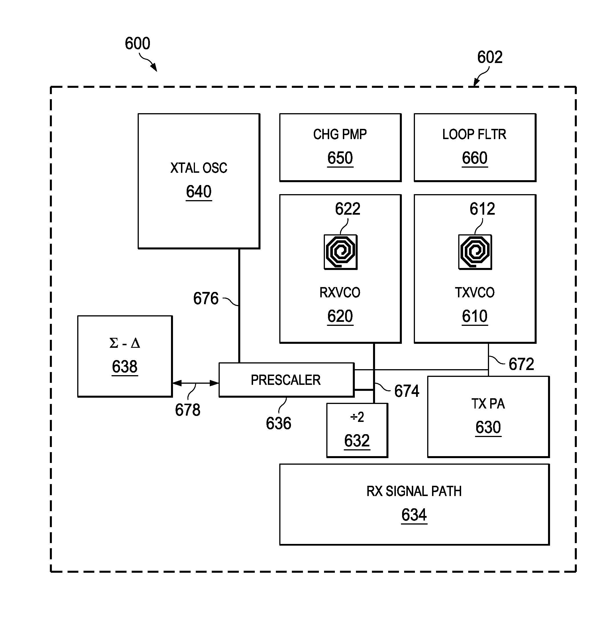
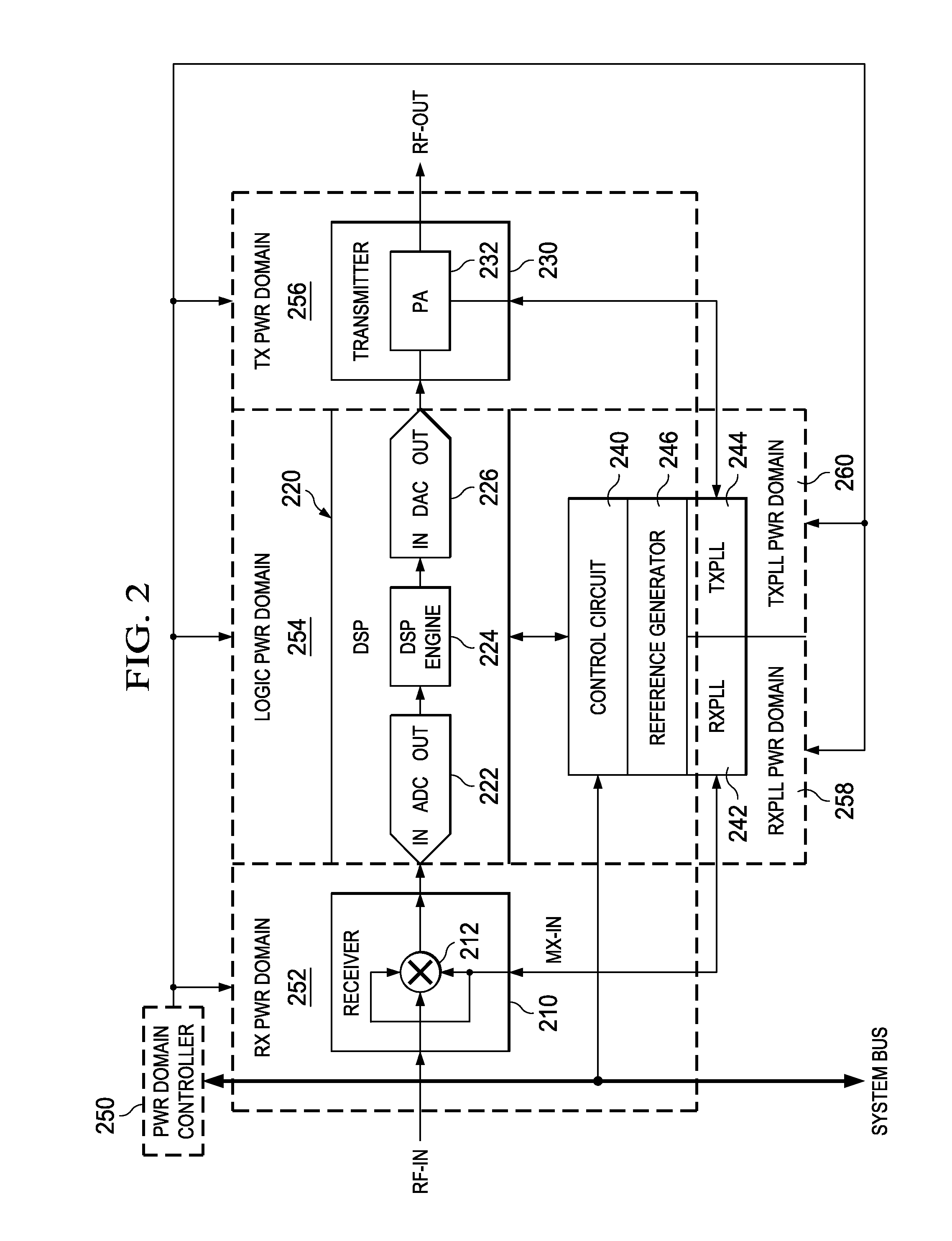
[0003]The problems noted above can be solved in large part by a dual synthesizer having shared components which, for example, provides a cost-effective solution for reducing substrate area and power requirements of an integrated circuit in which the dual synthesizer transceiver is formed. A dual synthesizer having shared components system includes two separate frequency synthesizers that have at least one shared low frequency generation component that is shared between the two separate frequency synthesizers. The two frequency synthesizers are adapted to operate (respectively) in transmit (TX) and receive (RX) modes and can be arranged to optimize the phase noise differently in accordance with the TX and RX requirements associated with each mode. The two frequency synthesizers are also adapted to provide built-in self-test signals used for intermodulation testing and calibration, including tuning of various high frequency selective impedance points, as well as low frequency analog baseband signal processing blocks (such as filters and amplifiers etc.), thus leading to a high sensitivity and high selectivity receiver implementation at minimum additional cost.

Problems solved by technology

Further, the Summary is not intended to identify key features or essential features of the claimed subject matter, nor is it intended to be used as an aid in determining the scope of the claimed subject matter.

Method used


Image

  • Self-calibrating shared-component dual synthesizer
  • Self-calibrating shared-component dual synthesizer
  • Self-calibrating shared-component dual synthesizer

Examples


Embodiment Construction

[0011]The following discussion is directed to various embodiments of the invention. Although one or more of these embodiments may be preferred, the embodiments disclosed should not be interpreted, or otherwise used, as limiting the scope of the disclosure, including the claims. In addition, one skilled in the art will understand that the following description has broad application, and the discussion of any embodiment is meant only to be example of that embodiment, and not intended to intimate that the scope of the disclosure, including the claims, is limited to that embodiment.

[0012]Certain terms are used throughout the following description—and claims—to refer to particular system components. As one skilled in the art will appreciate, various names may be used to refer to a component or system. Accordingly, distinctions are not necessarily made herein between components that differ in name but not function. Further, a system can be a sub-system of yet another system. In the follow...


PUM


Abstract

A self-calibrating shared-component dual synthesizer includes, for example, two frequency synthesizers that are adapted to operate (respectively) in transmit (TX) and receive (RX) modes. Each synthesizer can be selectively arranged to vary and optimize the phase noise in accordance with the TX and RX requirements associated with each mode as well as independently optimized for flexible low area floorplan to achieve low power, spectral fidelity and reduced test time, low cost built in self-calibration. The two frequency synthesizers are also adapted to provide a built-in self-test signals used for intermodulation testing and calibration.

Description

BACKGROUND[0001]Modern electronic systems such as radio-enabled systems often have low power dissipation requirements while operating in transmit and / or receive modes. These systems also often require a self-testing and self-calibration capability that is cost effective. To save cost, the substrate area of an integrated circuit (IC) used to implement a self-test and self-calibration capability for a radio device such as a transceiver is often minimized by using as single frequency synthesizer from which receive and transmit clock signals are derived. Such an approach often requires complicated clock distribution schemes that consume relatively large amounts of power and that use additional buffers, which significantly degrades the dynamic range of the system.[0002]In products that have the need to perform built-in self-calibration (BISC) of various parameters of the receiver, a lower-performance oscillator can be included on the substrate circuitry in order to save area of the subst...

Claims


Application Information

Patent Timeline
Patent Type & Authority Applications(United States)
IPC IPC(8): H04B17/14H04B17/24H04B17/21H03L7/099H03L7/08
CPCH04B17/14H03L7/099H04B17/24H04B17/21H03L7/0802H03L7/0891H03L7/104H03L7/18H03L7/235H04B1/403H04B1/408H04B1/50
Inventor CHAKRABORTY, SUDIPTOGRAUL, JENS
Owner TEXAS INSTR INC
Why Eureka
Try Eureka