Inline motorized lock drive for solenoid replacement

a solenoid replacement and motorized lock technology, applied in the field of electromechanical locks, can solve the problems of labor-intensive and costly installation and interconnection of sensors during manufacturing, and the inside cannot be prevented from exiting the secure area, and achieves the effect of reducing torque and power, reliably operating the drive, and low voltage very efficien

Active Publication Date: 2015-07-02
SARGENT MANUFACTURING CO INC
View PDF10 Cites 32 Cited by
  • Summary
  • Abstract
  • Description
  • Claims
  • Application Information

AI Technical Summary

Benefits of technology

[0051]In a further aspect, the motor is a DC motor operable on less than five volts. Preferably the DC voltage of the motor is 2 volts. This low voltage is very efficient, and the inline aspect of the invention allows the reduced torque and power of the motor to reliably operate the drive, while also allowing an extremely small size, as needed to fit within the limited space available inside the lock housing when the motor is oriented with its axis inline with the slide axis of the locking element.

Problems solved by technology

The lock mechanism is designed to prevent unauthorized entry into the secured area from a hallway or public area, but does not prevent those within from exiting the secure area.
Unless a key is used to manually operate the fail secure lock, it is not possible to enter the secured area even when power is intentionally cut to the lock mechanism.
One problem with the solenoid drive system for locks is that each of the four different types of locks (12 and 24 volt solenoids in fail safe and fail secure models) must be manufactured and held in inventory to meet the needs of customers.
A related problem is that the four solenoid-type lock drives often require several components and / or internal connections within the lock mechanism.
The installation and interconnection of these sensors during manufacturing is labor intensive and costly.
Another problem with such prior art solenoid-type lock drives is the waste of power due to the need to keep the solenoid constantly powered.
A related problem is that by constantly supplying power to a solenoid lock (to hold it in the non-default state), the lock is continuously dissipating power in the solenoid coil, which results in heating of the lock body.
Although the lock and the solenoid coil can be designed for the heating produced in continuous duty operation, this heating is generally considered to be objectionable.
The handle connected to such a lock may become objectionably warm and the heating may affect any nearby electronic components.
As such, low cost has been a primary motivating factor and energy conservation has not been properly considered.
However low power motorized designs do not operate against a biasing spring that returns the lock to a default state.
Motorized drive type locks are typically used in more expensive applications, such as in low power battery operated lock applications which use an electronic key.
However, it has been found that the mechanical efficiency of conventional motorized locks is also less than is desirable.
This reduced mechanical efficiency results in an undesirable excess power loss each time the lock changes state due to the need to overcome excess friction.
It has not heretofore been recognized that this offset and the interconnecting element produce significant friction that must be overcome and decreased performance.
However, motorized lock drives do not rely upon the lock to return to a default state and cannot be used to replace a solenoid lock controlled by a solenoid-type lock control system.
Thus a solenoid-type lock control system is significantly different from a motorized drive lock control system and a lock mechanism with a motorized lock drive is not suitable for use with the control system for a lock mechanism having a solenoid-type lock drive.
However, a lock mechanism having a motorized lock drive of the type described above cannot directly replace a solenoid-type lock due to the differences between the required control systems.

Method used


Image

  • Inline motorized lock drive for solenoid replacement
  • Inline motorized lock drive for solenoid replacement
  • Inline motorized lock drive for solenoid replacement

Examples


Embodiment Construction

)

[0072]In describing the preferred embodiment of the present invention, reference will be made herein to FIGS. 1-18 of the drawings in which like numerals refer to like features of the invention.

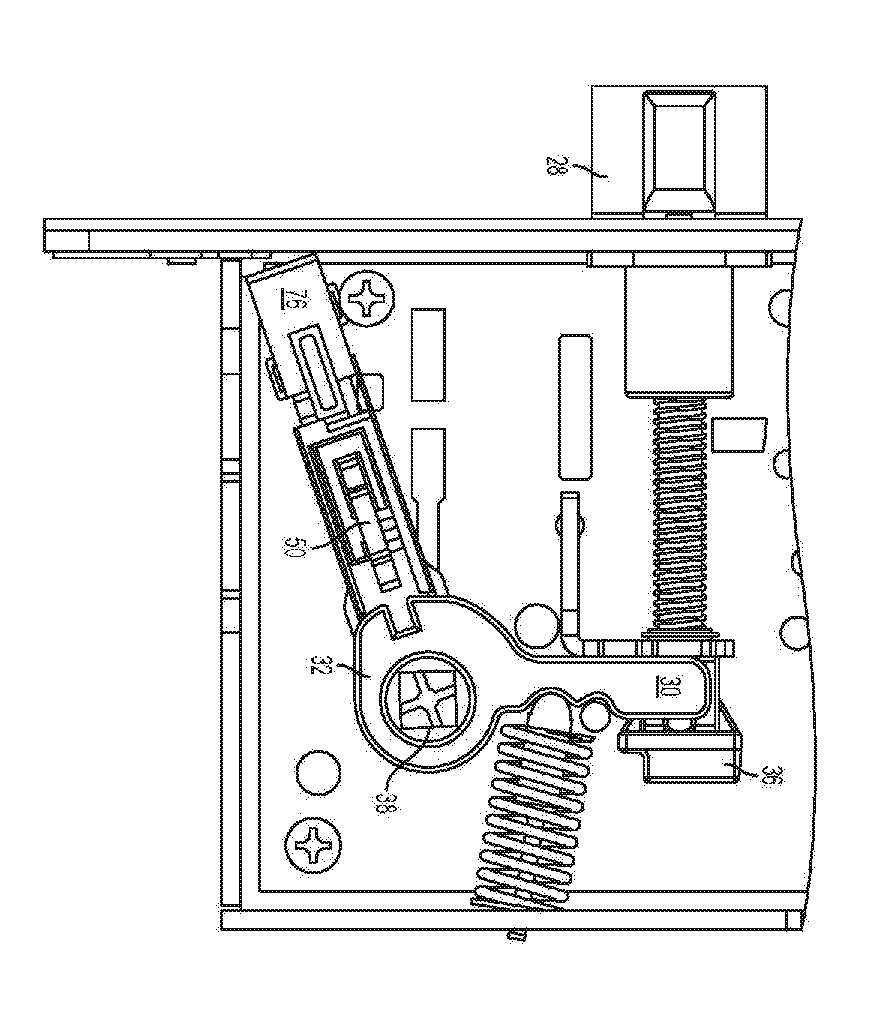
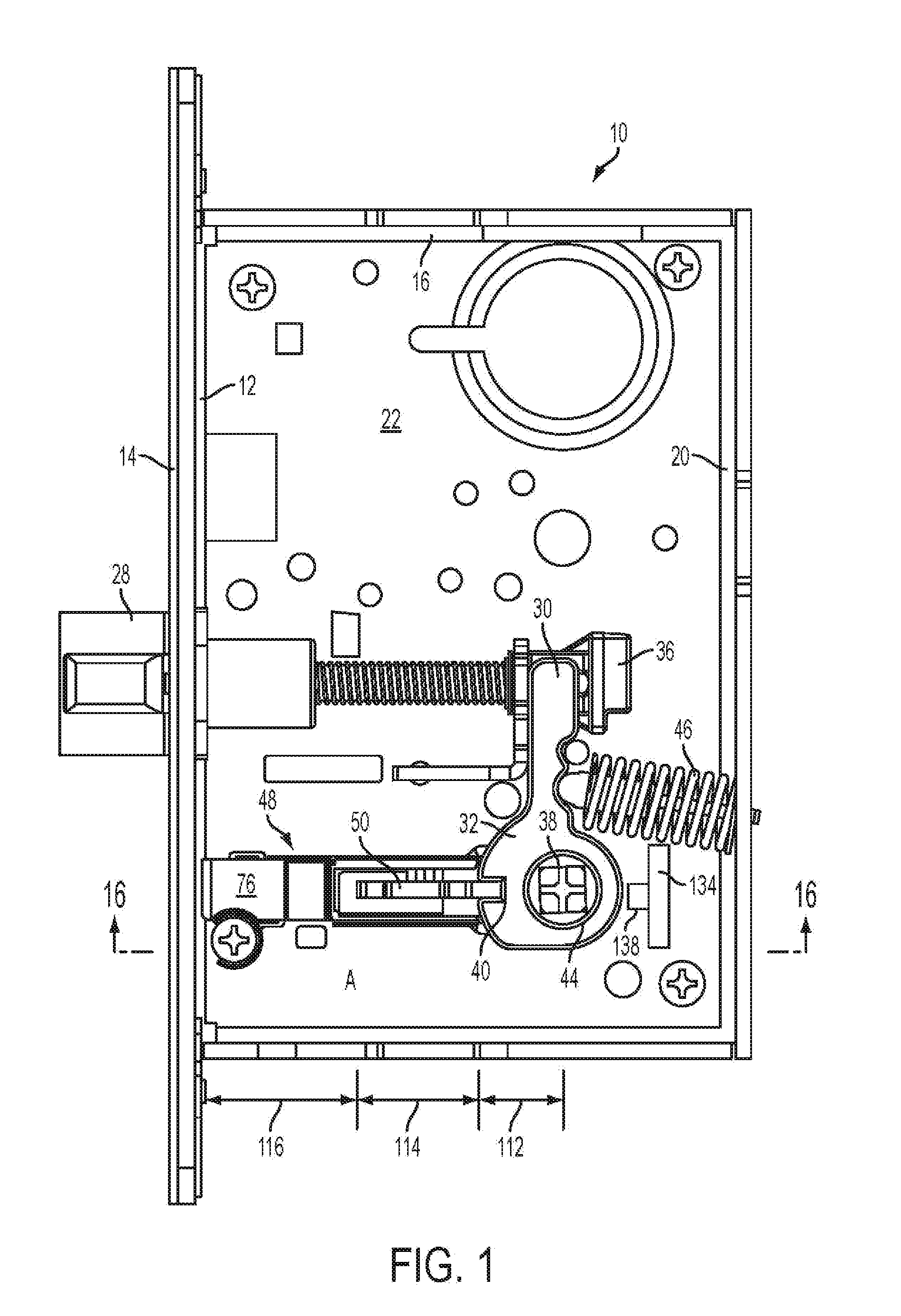
[0073]Referring to FIG. 1, a mortise lock 10 includes a front wall 12, preferably covered by a decorative face plate 14, a top wall 16, a bottom wall 18, a back wall 20 and a left side wall 22. The five walls and plates 12, 16, 18, 20 and 22 are preferably formed from a single sheet with the surrounding walls being bent upwards to form an open rectangular body for the lock housing. The lock body holds the internal lock components within it and the body is then enclosed with a removable cover plate 24 on the right side to form the final wall of the complete lock housing.

[0074]The cover plate 24 forming the right side of the lock housing has been removed in FIG. 1 to show various internal components of the lock, including the location of the inline motorized lock drive 26 of the present invent...


PUM


Abstract

An inline motorized lock drive is mountable within a lock housing to drive a sliding locking element between a locked and unlocked position. The lock drive includes a reversible motor having a shaft with an augur thereon to drive a lock spring, which drives the locking element. The sliding motion of the locking element is axially aligned with the motor axis to substantially reduce friction. The lock drive is preferably modular and emulates a solenoid lock drive with a control circuit. The control circuit is connected to drive the motor is switchable to default to a locked position or an unlocked position and emulate a “fail safe” or a “fail secure” type solenoid lock drive. The control circuit operates on 12 or 24 volts to replace solenoid locks of either voltage and stores power when power is applied, then uses the stored power to return the lock drive to the selected default state when power is removed.

Description

TECHNICAL FIELD[0001]The present invention relates to electromechanical locks having a lock drive that switches the lock between a locked state and an unlocked state responsive to an electrical signal. More specifically, the invention relates to improving the electrical and mechanical efficiency of the lock drive. The invention further relates to improving manufacturability of such locks.BACKGROUND ART[0002]There is a very large installed base of solenoid-type electromechanical locks. Solenoid-type locks use a solenoid as the lock drive to move a locking element within the lock between a locked position and an unlocked position. In the locked position, the locking element is moved into interfering engagement with a lock component to prevent retraction of the latchbolt. In the unlocked position, the locking element is moved to a position that allows the latchbolt to be freely retracted.[0003]The solenoid in a solenoid-type lock drive is typically powered by a solenoid lock control sy...

Claims


Application Information

Patent Timeline
Patent Type & Authority Applications(United States)
IPC IPC(8): E05B63/08E05C1/08E05B47/00
CPCE05B63/08E05C1/08E05B47/0012E05B47/0673E05B2047/003E05B2047/0031E05B2047/0073E05B2047/0076E05B2047/0058Y10T292/1021E05B47/0004
Inventor ELLIS, DAVID D.LOWDER, SCOTT B.
Owner SARGENT MANUFACTURING CO INC
Why Eureka
Try Eureka