Gas Turbine Energy Storage and Energy Supplementing Systems And Methods of Making and Using the Same

Inactive Publication Date: 2015-07-02
POWERPHASE
View PDF15 Cites 35 Cited by
  • Summary
  • Abstract
  • Description
  • Claims
  • Application Information

AI Technical Summary

Benefits of technology

[0025]Another advantage of the present invention is the ability to use a resistance type heater in the hot fluid tank to be able to adjust the power output of the gas turbine system instead of turning down the gas turbine system itself. Another advantage of the present invention is the ability to use a resistance type heater in the hot fluid tank to be able to provide rapid grid stability control.
[0026]Another advantage of the present invention is the ability to incorporate selective portions of the embodiments on existing gas turbines to achieve specific plant objectives.
[0027]Another advantage of preferred embodiments is the ability to incorporate all or portions of the invention into existing bleed systems on gas turbine systems that are used for various reasons that will result in simpler installation and lower costs.
[0028]Another advantage of the present embodiment is the ability to inject the air from the storage tank and/or the boost compressor into a turbine cooling circuit, thus recovering all of the heat given up by cooling the air for the storage process is not necessary because cool cooling air is highly desirable.
[0029]Accordingly, the In situ Gas Turbine Energy Storage (“IGTES”) system according to one preferred embodiment of the present invention includes an intercooled compression circuit using an air booster pump to produce compressed air that is stored in high pressure air tanks, where the intercooling process heat absorbed from the compressed air is introduced to ambient air and then delivered to the inlet of the gas turbine to improve low flow efficiency and turn down capability of the gas turbine co

Problems solved by technology

Unfortunately, because industrial gas turbines, which represent the majority of installed base, were designed primarily for base load operation, when they are cycled, a severe penalty is associated with the maintenance cost of that particular unit.
That same cost could be incurred in one year for a plant that is forced to start up and shut down every day.
Maintaining safe compressor operation and emissions typically limit the level of turn down that can be practically achieved.
This has a negative impact on the efficiency of the system as the work performed on the air that is bled off is lost.
Additionally, the combustion system also presents a limit to the system.
The combu

Method used


Image

  • Gas Turbine Energy Storage and Energy Supplementing Systems And Methods of Making and Using the Same
  • Gas Turbine Energy Storage and Energy Supplementing Systems And Methods of Making and Using the Same
  • Gas Turbine Energy Storage and Energy Supplementing Systems And Methods of Making and Using the Same

Examples


Example

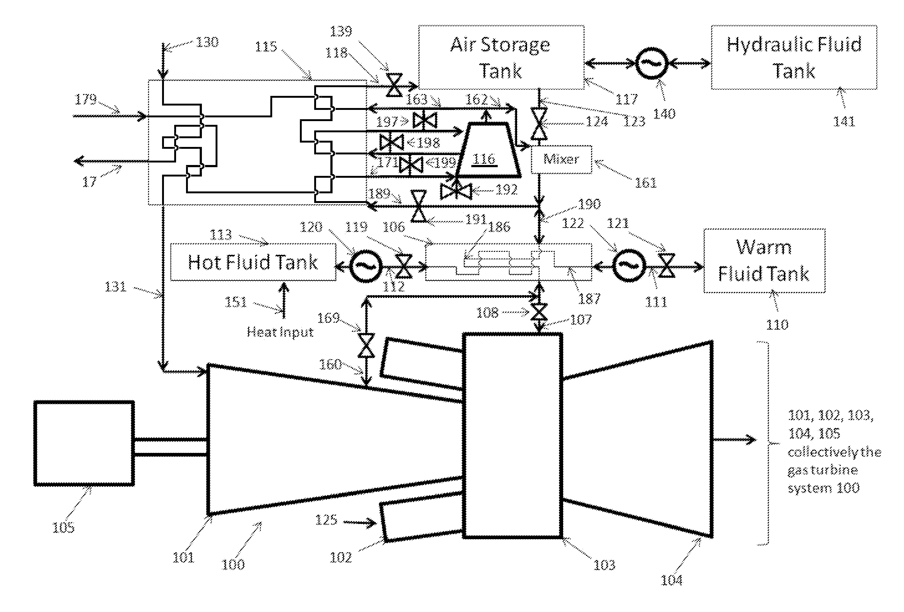
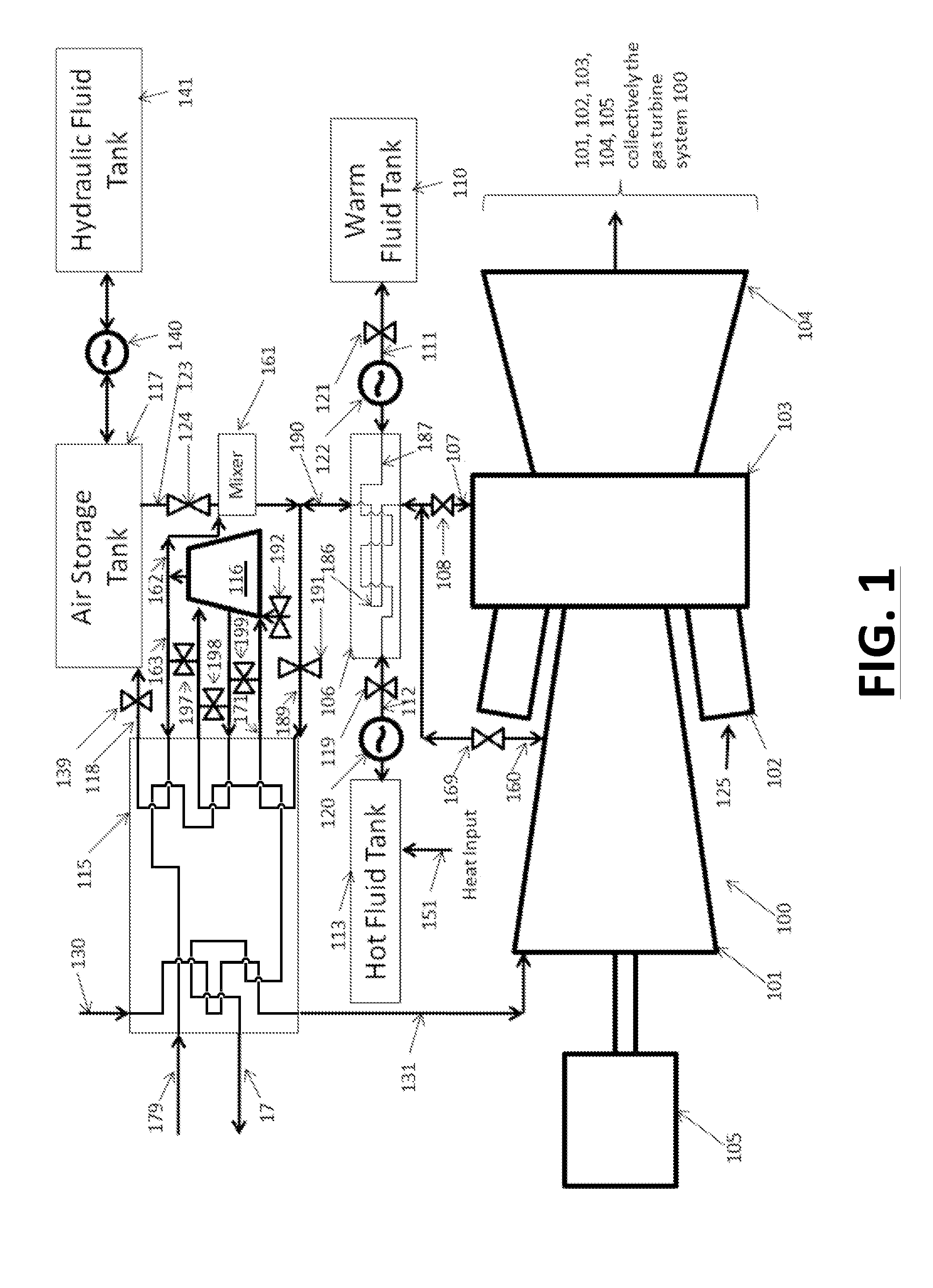
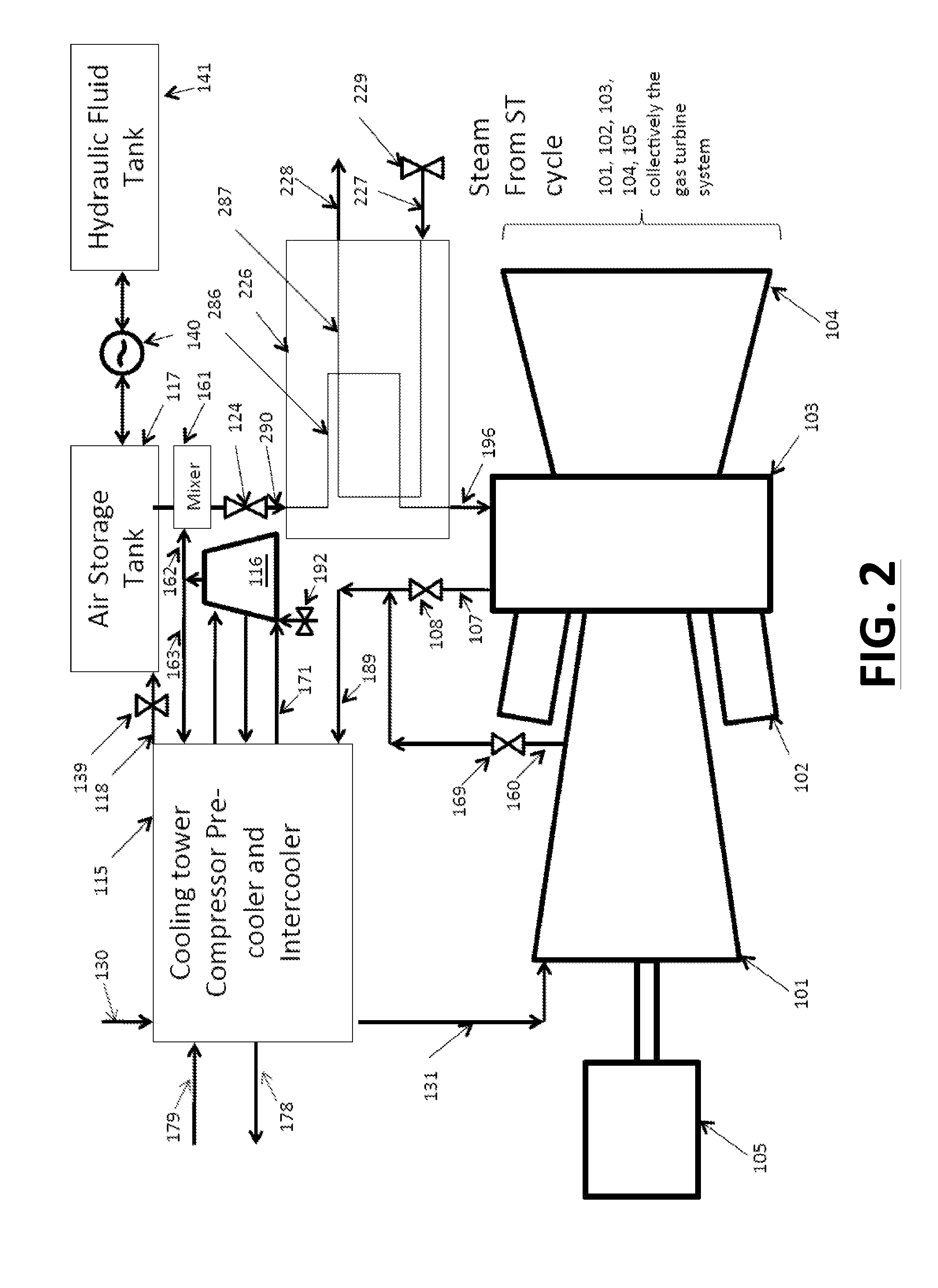
[0046]One aspect of the invention relates to methods and systems that allow gas turbine systems to run more efficiently under various conditions or modes of operation. In systems such as the one discussed in U.S. Pat. No. 6,305,158 to Nakhamkin (the “'158 patent”), there are three basic modes of operation defined, a normal mode, charging mode, and an air injection mode, but it is limited by the need for an the gas turbine and electrical generator that has the capacity to deliver power “exceeding the full rated power” that the gas turbine system can deliver. The limitation of “exceeding the full rated power” arises from an early patent for air injection into gas turbines, U.S. Pat. No. 2,535,488 issued in 1950 to Dros, which discloses that gas turbines lose power as ambient temperature rises and that there is excess capacity within the existing gas turbine. There are several elements to a gas turbine that limit its “rated power” in its unaltered state, specifically, flow limits, mech...


PUM


Abstract

The current invention provides several options, depending on specific plant needs, to improve the efficiency and power output of a plant at low loads, reduce the lower limit of power output capability of a gas turbine while at the same time increasing the upper limit of the power output of the gas turbine, thus increasing the capacity and regulation capability Of a new or existing gas turbine system. One aspect of the present invention relates to an energy storage and retrieval system for obtaining useful work from an existing source of a Gas Turbine (GT) power plant while preferably providing an efficient heated air inlet charger.

Description

FIELD OF THE INVENTION[0001]The invention relates generally to electrical power systems, including generating capacity of a gas turbine, and more specifically to energy storage that is useful for providing additional electrical power during periods of peak electrical power demand while self consuming power generated by the gas turbine during times of reduced power demand.BACKGROUND OF THE INVENTION[0002]Currently most marginal energy is produced mainly by gas turbine, either in simple cycle or combined cycle configurations. As a result of load demand profile, the gas turbine base systems are cycled up during periods of high demand and cycled down or turned off during periods of low demand. This cycling is typically driven by the Grid operator under a program called active grid control, or “AGC”. Unfortunately, because industrial gas turbines, which represent the majority of installed base, were designed primarily for base load operation, when they are cycled, a severe penalty is ass...

Claims


Application Information

Patent Timeline
IPC IPC(8): F02C9/18F01D25/10
CPCF01D25/10F02C9/18F02C6/18F02C7/08F05D2270/053Y02E20/14Y02E20/16Y02E60/16F02C6/16F02C7/18
Inventor KRAFT, ROBERT JSOBIESKI, PETE
Owner POWERPHASE
Why Eureka
Try Eureka