Vacuum Loss Detection During Laser Eye Surgery

Active Publication Date: 2015-07-09
AMO DEVMENT
View PDF2 Cites 30 Cited by
  • Summary
  • Abstract
  • Description
  • Claims
  • Application Information

AI Technical Summary

Benefits of technology

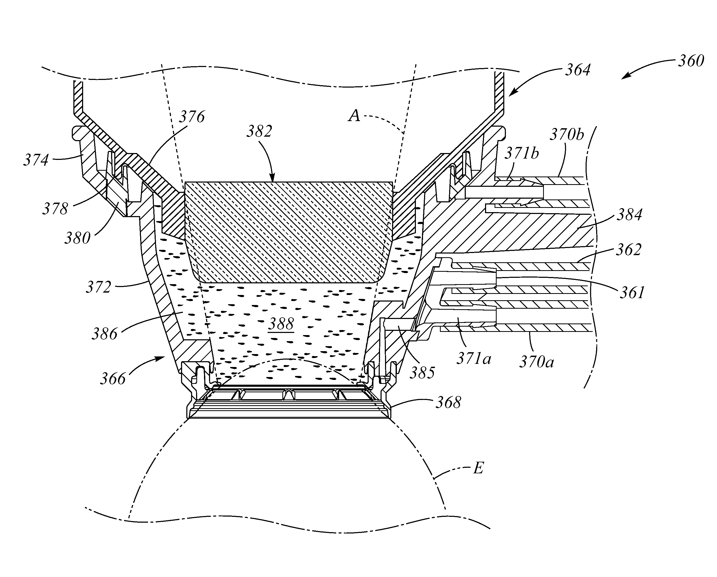
[0011]The improved methods and apparatus for retention of an eye as described herein can be used to provide safe and effective retention for surgery such as laser eye surgery. The retention structure may comprise an annular structure to couple to an anterior surface of the eye, such as one or more of the cornea, the limbus, or the conjunctiva. The annular structure can be coupled to a suction line so as to couple the annular structure to the eye with suction. In many embodiments, a coupling sensor is coupled to one or more of the annular structure or the suction line to determine coupling of the retention structure to the eye, such that coupling of the retention structure to the eye can be measured quickly. The determination of coupling of the retention structure to the eye can be provided to the surgeon so that the surgeon can take appropriate action, and may allow the laser treatment to be paused or interrupted. A fluid collecting container can be coupled to the annular structure to receive and collect liquid or viscous material from the container. A fluid stop comprising a float valve or a porous structure can be coupled to an out

Problems solved by technology

However, prior methods and apparatus of cutting can be less than desirable and provide less than ideal results in at least some instances.
Although lasers having pulse short pulse durations have been proposed to cut tissue, these short pulsed lasers may use very high pulse repetition rates and the energy of these lasers can be difficult to measure in at least some instances.
Many patients may have visual errors associated with the refractive properties of the eye such as nearsightedness, farsightedness and astigmatism.
The cataract scatters light passing through the lens and may perceptibly degrade vision.
Early in the development of an age-related cataract the power of the lens may increase, causing near-sightedness (myopia).
Cataract formation may often progresses slowly resulting in progressive vision loss.
Although prior methods and apparatus have been proposed to cut tissue, the fixation of tissue of these prior methods and apparatus can be less than ideal in at least some respects.
For example, the prior microkeratomes that have been used to cut corneal tissue with blades can result in less than ideal fixation of the eye, and m

Method used


Image

  • Vacuum Loss Detection During Laser Eye Surgery
  • Vacuum Loss Detection During Laser Eye Surgery
  • Vacuum Loss Detection During Laser Eye Surgery

Examples


Embodiment Construction

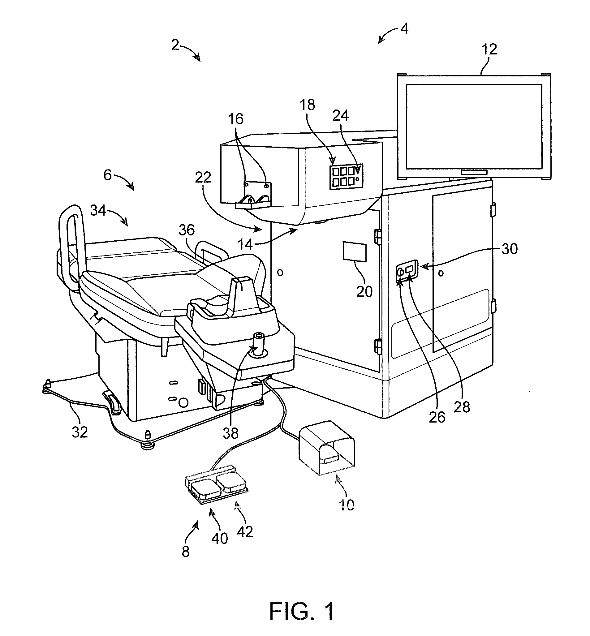
[0032]Methods and systems related to laser eye surgery are disclosed. In many embodiments, a laser is used to form precise incisions in the cornea, in the lens capsule, and / or in the crystalline lens nucleus. Although specific reference is made to tissue retention for laser eye surgery, embodiments as described herein can be used in one or more of many ways with many surgical procedures and devices, such as orthopedic surgery, robotic surgery and microkeratomes.

[0033]The embodiments as describe herein are particularly well suited for treating tissue, such as with the surgical treatment of tissue. In many embodiments, the tissue comprises an optically transmissive tissue, such as tissue of an eye. The embodiments as described herein can be combined in many ways with one or more of many known surgical procedures such as cataract surgery, laser assisted in situ keratomileusis (hereinafter “LASIK”), laser assisted subepithelial keratectomy (hereinafter “LASEK”).

[0034]Methods and systems...


PUM


Abstract

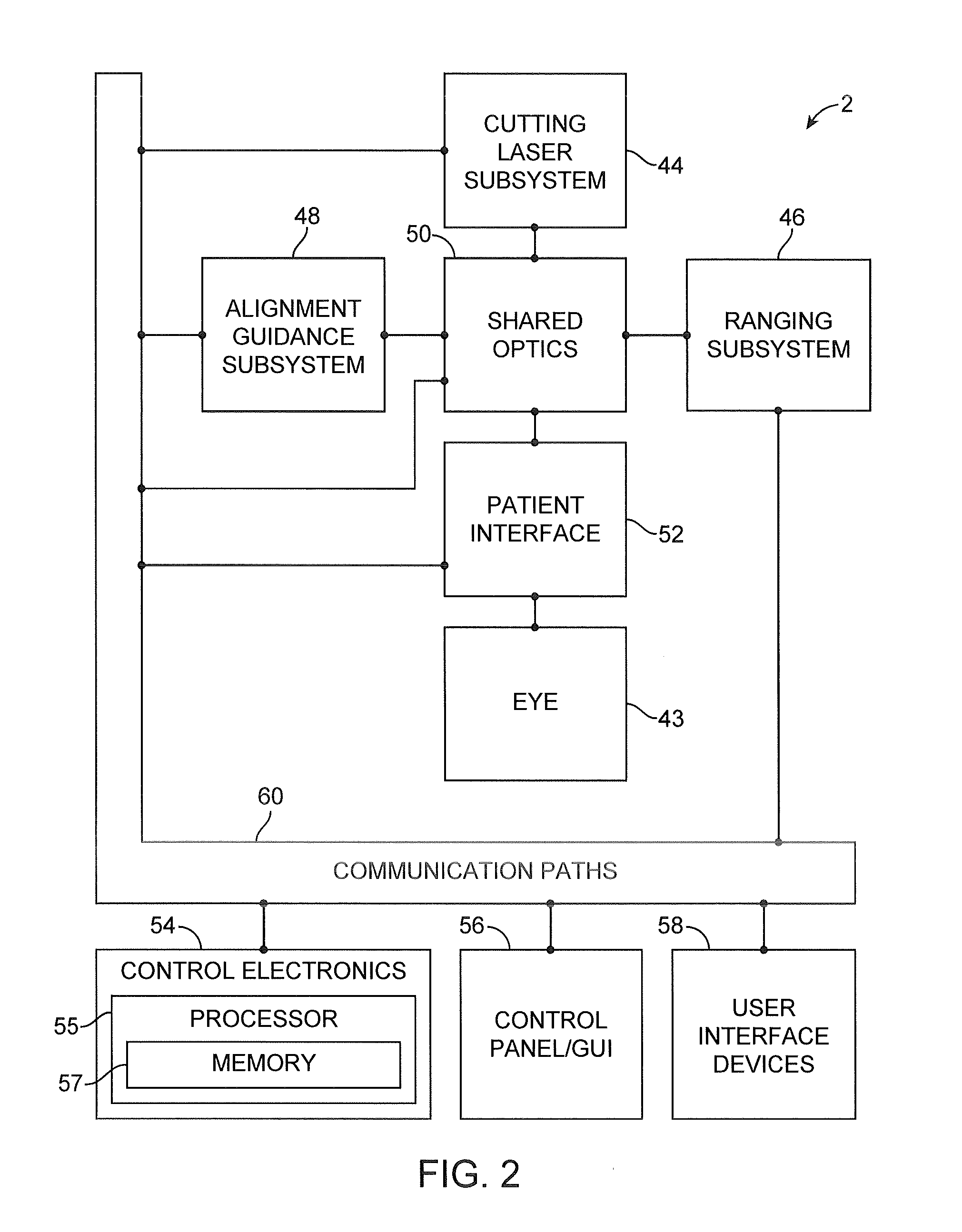
Apparatus to treat an eye with an ophthalmic laser system comprises a patient interface having an annular retention structure to couple to an anterior surface of the eye. The retention structure is coupled to a suction line to couple the retention structure to the eye with suction. Liquid is added above the eye to act as a transmissive medium. A coupling sensor is coupled to the suction line to determine coupling of the retention structure to the eye. A separate pressure monitoring circuit having a much smaller volume than the suction line is connected to the annular retention structure to measure suction pressure therein. A system processor coupled to the monitoring pressure sensor includes instructions to interrupt firing of a laser when the pressure measured with a monitoring pressure sensor rises above a threshold amount.

Description

CROSS-REFERENCE TO RELATED APPLICATIONS[0001]This application is a continuation-in-part of co-pending U.S. patent application Ser. No. 14 / 068,994, filed Oct. 31, 2013, which claims the benefit of priority to U.S. Provisional Application No. 61 / 721,693, filed Nov. 2, 2012.FIELD OF THE INVENTION[0002]The present disclosure relates generally to surgery. Although specific reference is made to tissue retention for laser eye surgery, embodiments as described herein can be used in one or more of many ways with many surgical procedures and devices, such as orthopedic surgery, robotic surgery and microkeratomes.BACKGROUND OF THE INVENTION[0003]Cutting of materials can be done mechanically with chisels, knives, scalpels and other tools such as surgical tools. However, prior methods and apparatus of cutting can be less than desirable and provide less than ideal results in at least some instances. For example, at least some prior methods and apparatus for cutting materials such as tissue may pr...

Claims


Application Information

Patent Timeline
IPC IPC(8): A61F9/009A61M1/00A61F9/008
CPCA61F9/009A61F9/008A61M1/0052A61F2009/00851A61F2009/0087A61M2205/3344A61F9/00825A61M1/0025A61M1/0031A61M1/005A61M2210/0612A61F2009/00872A61M1/73A61M1/782A61M1/784A61M1/74
Inventor GOODING, PHILLIPBELTRAN, CHRISTINECAMPOS, MICHAELWYSOPAL, JANEIKANAS, BRENT
Owner AMO DEVMENT
Why Eureka
Try Eureka