
Method of producing a veneered element

a technology of veneered elements and veneers, which is applied in the field of producing veneered elements, can solve the problems of high production cost, low impact resistance of wood veneer, and inability to sand the wood veneer layer, so as to reduce the flow of the sub-layer, reduce the amount of free binder, and reduce the fluid pressure

Active Publication Date: 2015-07-16
VÄLINGE INNOVATION AB
View PDF13 Cites 65 Cited by
  • Summary
  • Abstract
  • Description
  • Claims
  • Application Information

AI Technical Summary

Benefits of technology

The patent aims to improve the durability of a veneer surface. This can be achieved by creating a continuous or patchwork of veneers and using a sub-layer to fill the gaps between them. The technical effect is a more durable, long-lasting veneer surface.

Problems solved by technology

However, a wood veneer layer cannot be sanded as a solid wood or engineered wood flooring can be.
A wood veneer may have a lower impact resistance than laminate floorings and the production cost is high, compared to laminate floorings, when high quality veneers are to be used.
When heat and pressure is applied, the result is the formation of a panel, with the surface layer of the particles filling whatever flaws or holes would otherwise the present in the veneer.
However, the same material and problems applies for other types of building panels such as wall panels, ceiling panels, and for furniture components.
Abrasive machining and / or brushing the veneer layer may enlarge existing holes, cavities and / or cracks, and / or form new holes, cavities and / or cracks.
Both surfaces, or only one of the surfaces, of the veneer layer, may be machined abrasively.
The cross-linking also results in solidification of a part of the sub-layer, thus further pressing remaining uncured binder of the sub-layer.
The fillers may reduce flowing of the sub-layer such that the sub-layer permeates more difficult through the veneer layer.
Furthermore, some fillers, for example, wood particles, absorb the binder to a certain degree, thereby reducing the amount of free binder, which may permeate through veneer layer, and thereby also reduce the fluid pressure.
Forming holes and cracks reduces resistance for the sub-layer for permeating through the veneer layer.
The fluid pressure may be non-uniformly distributed.
By the fluid pressure being non-uniformly distributed, the degree of permeation of the sub-layer may vary of the surface of the veneer and non-uniform pattern may be obtained.
The high-density portions do not absorb enough binder from the sub-layer to be locked by the hardened binder after pressing.

Method used


Image

  • Method of producing a veneered element
  • Method of producing a veneered element
  • Method of producing a veneered element

Examples


example 1

[0162]400 g / m2 of a powder mixture, comprising 40 wt-% wood fibres, 10 wt-% aluminium oxide (Alodur ZWSK 180-ST), 49.5 wt-% melamine formaldehyde resin (Kauramin 773) and 0.5 wt-% of carbon black (Printex 60), was scattered on a 10.0 mm HDF board for forming a sub-layer. The powder layer forming the sub-layer was sprayed with 20 g / m2 of an aqueous solution of a release agent (PAT-660). A 0.6 mm oak veneer layer was positioned on the sub-layer prior to pressing the assembly in a short cycle press for 30 seconds at 40 bar with a press plate temperature of 160° C. The resulting product was a veneered HDF having pores and cracks in the veneer layer filled with the cured powder mixture of the sub-layer.

example 2

[0163]800 g / m2 of a powder mixture, comprising of 40 wt-% wood fibres, 10 wt-% aluminium oxide (Alodur ZWSK 180-ST), 49.5 wt-% melamine formaldehyde resin (Kauramin 773) and 0.5 wt-% of carbon black (Printex 60), was scattered on a 10.0 mm HDF board for forming a sub-layer. The powder layer forming the sub-layer was sprayed with 20 g / m2 of an aqueous solution of a release agent (PAT-660). A 0.6 mm oak veneer was positioned on the sub-layer prior to pressing the assembly in a short cycle press for 30 seconds at 40 bar with a press plate temperature of 160° C. The resulting product was a veneered HDF having cracks and an increased amount of pores in the veneer layer filled with the cured powder mixture of the sub-layer in comparison with the product of example 1.

example 3

[0164]400 g / m2 of a powder mixture, comprising 17.5 wt-% wood fibres, 17.5 wt-% mineral fibres 10 wt-% aluminium oxide (Alodur ZWSK 180-ST), 52,5 wt-% melamine formaldehyde resin (Kauramin 773) and 0.5 wt-% of carbon black (Printex 60), was scattered on a 10.0 mm HDF board for forming a sub-layer. The powder layer forming the sub-layer was sprayed with 20 g / m2 of an aqueous solution of a release agent (PAT-660).

[0165]A 0.6 mm oak veneer was positioned on the sub-layer prior to pressing the assembly in a short cycle press for 30 seconds at 40 bar with a press plate temperature of 160° C. The resulting product was a veneered HDF having cracks and a decreased amount of pores in the veneer layer filled with the cured powder mixture of the sub-layer in comparison with the product of example 1.


PUM

PropertyMeasurementUnit
thicknessaaaaaaaaaa
thicknessaaaaaaaaaa
thickaaaaaaaaaa

Abstract

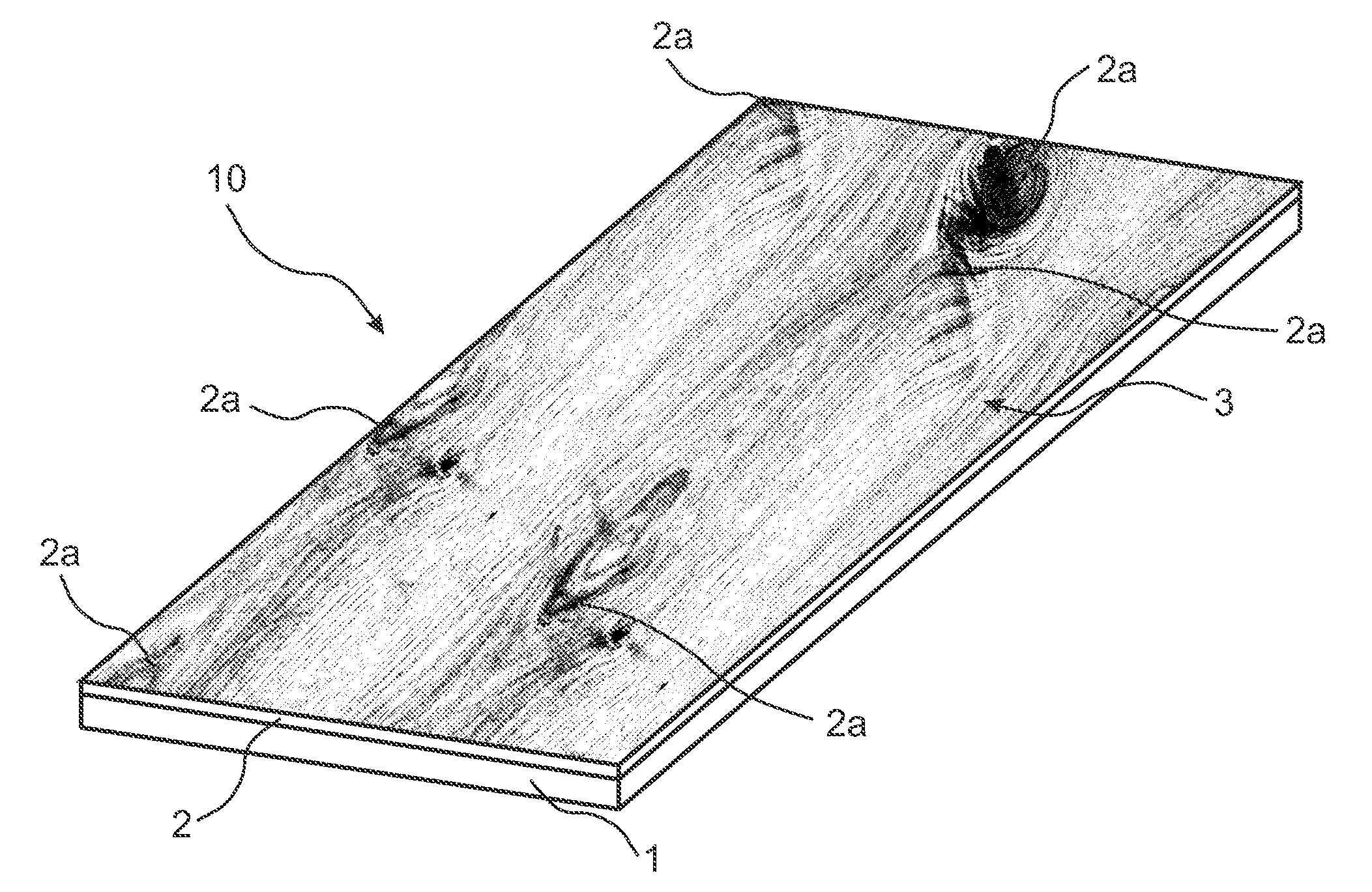
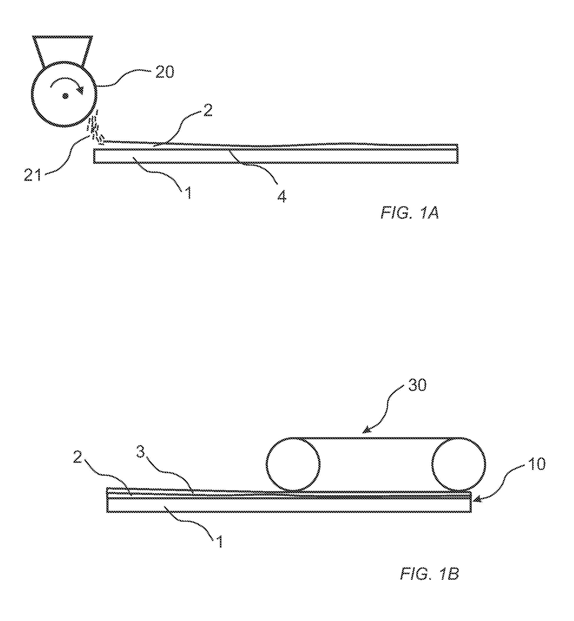
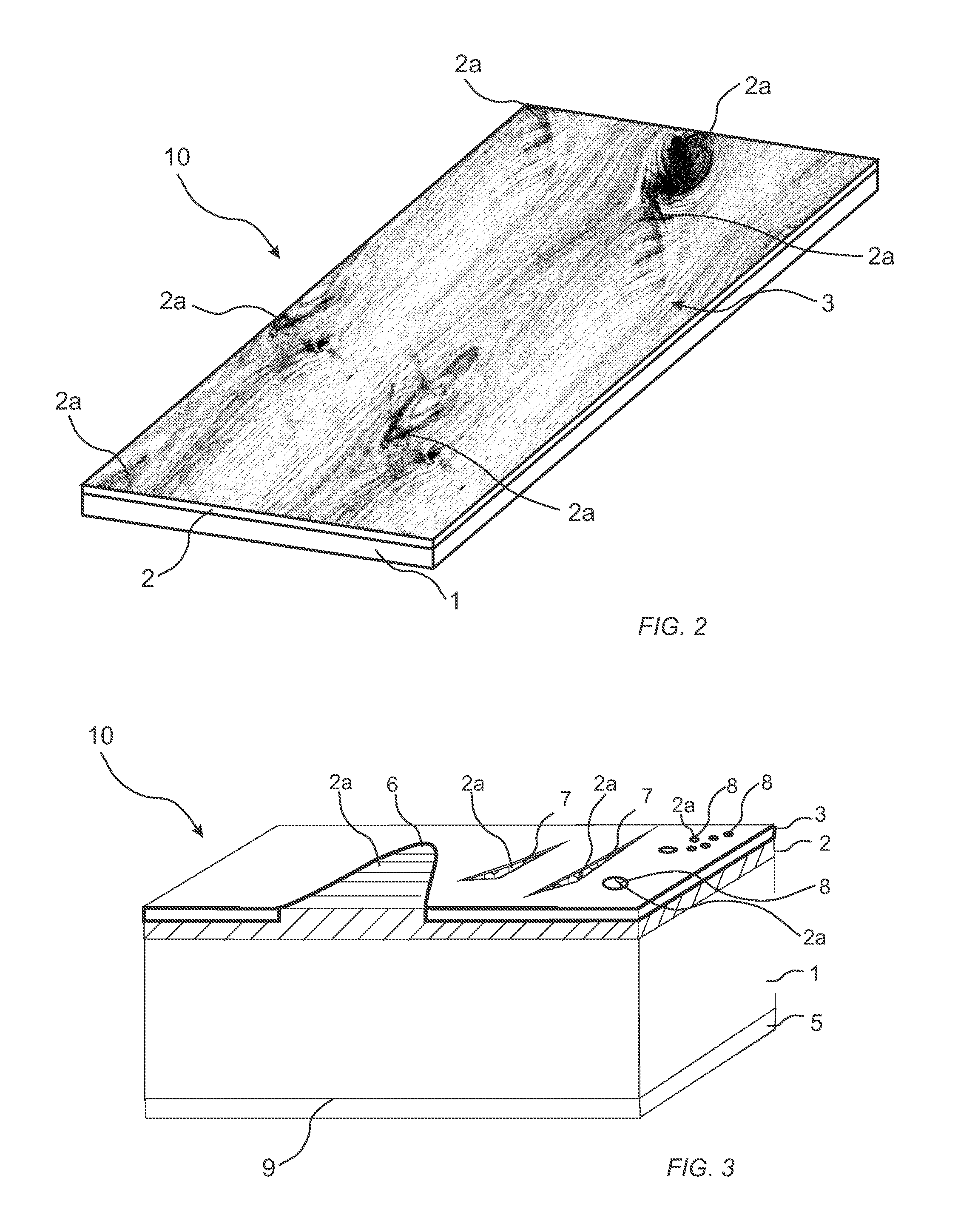
A method of producing a veneered element (10), including providing a substrate (1), applying a sub-layer (2) on a surface of the substrate (1), applying a veneer layer (3) on the sub-layer (2), and applying pressure to the veneer layer (3) and / or the substrate (1), such that at least a portion of the sub-layer (2) permeates through the veneer layer (3). Also, such a veneered element (10).

Description

CROSS REFERENCE TO RELATED APPLICATIONS[0001]The present application claims the benefit of Swedish Application No. 1450023-5, filed on Jan. 10, 2014, the benefit of Swedish Application No. 1450552-3, filed on May 12, 2014, and the benefit of Swedish Application No. 1451154-7, filed on Sep. 29, 2014. The entire contents of each of Swedish Application No. 1450023-5, Swedish Application No. 1450552-3, and Swedish Application No. 1451154-7 are hereby incorporated herein by reference in their entirety.TECHNICAL FIELD[0002]The disclosure relates to a method of producing a veneered element and such a veneered element.TECHNICAL BACKGROUND[0003]Floor coverings having a wooden surface may be of several different types. Solid wood flooring is formed of a solid piece of wood in form of a plank. Engineered wood flooring is formed of a surface layer of wood glued to a core. The core may be a lamella core or a wood-based panel such as plywood, MDF or HDF. The wooden surface layer may as an example...

Claims


Application Information

Patent Timeline
Patent Type & Authority Applications(United States)
IPC IPC(8): E04F15/04E04F15/08B32B37/18B32B38/06B32B37/10B32B37/12
CPCE04F15/045B32B37/10E04F15/082B32B37/18B32B38/06B32B37/1284B27G1/00B27N3/005B27N3/02B27N3/04B27N3/08B27N7/005B32B3/30B32B5/142B32B21/02B32B21/08B32B21/14B32B27/20B32B27/42B32B2262/067B32B2264/062B32B2266/0214B32B2266/0285B32B2266/14B32B2305/073B32B2307/4026B32B2307/554B32B2317/02B32B2317/16B32B2471/00B32B2607/00B44C1/24B44C5/043B44C5/0438E04F15/042E04F15/085Y10T156/10Y10T156/1039Y10T428/24132Y10T428/24298Y10T428/24314Y10T428/24322Y10T428/24331Y10T428/24339Y10T428/24521Y10T428/24603Y10T428/24612Y10T428/24802Y10T428/24893Y10T428/24992Y10T428/249925Y10T428/24994Y10T428/24995Y10T428/249959Y10T428/249982Y10T428/249985Y10T428/249986Y10T428/249987Y10T428/25Y10T428/253Y10T428/256Y10T428/257Y10T428/3167Y10T428/31862Y10T428/31866Y10T428/31957Y10T428/31989B32B3/06
Inventor ZIEGLER, GORANNYGREN, PERMEIJER, THOMAS
Owner VÄLINGE INNOVATION AB
Learn More