Burner

a burner and burner technology, applied in the field of burners, can solve the problems of unburned fuel, insufficient air supplied to the burner, and a portion of the fuel supplied to the burner is exhausted in an unburned state, so as to reduce the quantity of unburned fuel discharged from the burner and improve the mixing efficiency of fluids

Inactive Publication Date: 2015-07-23
HINO MOTORS LTD
View PDF24 Cites 7 Cited by
  • Summary
  • Abstract
  • Description
  • Claims
  • Application Information

AI Technical Summary

Benefits of technology

[0027]In the another aspect of the burner according to the present disclosed technique, the pressure upstream of the baffle plate is appropriately adjusted. Since the mixing efficiency of fluid is improved, the quantity of unburned fuel discharged from the burner is reduced.

Problems solved by technology

In this fuel and air supply system, however, sufficient air is not supplied to fuel, and a portion of the fuel supplied to the burner is exhausted in an unburned state.

Method used


Image

  • Burner
  • Burner
  • Burner

Examples


first embodiment

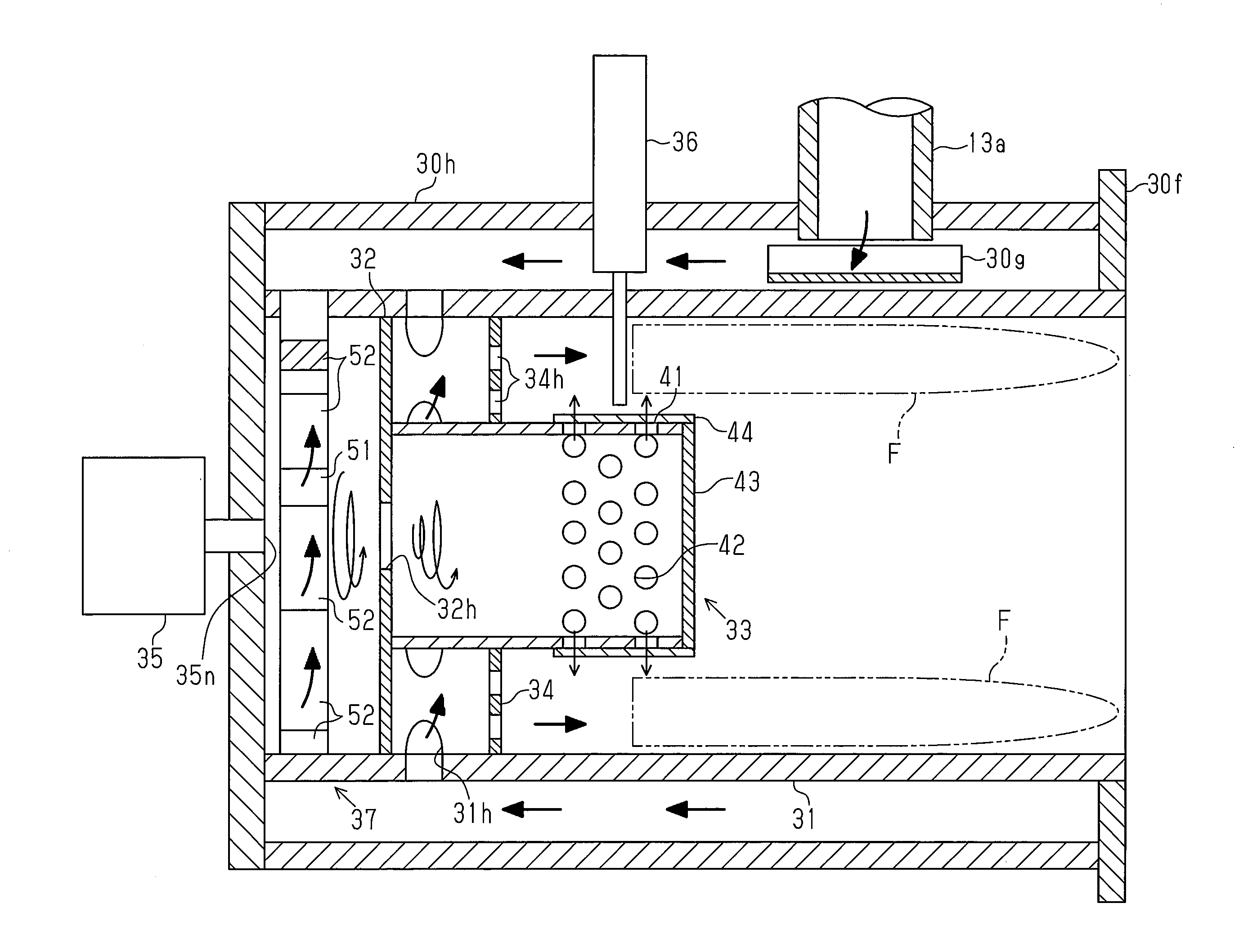
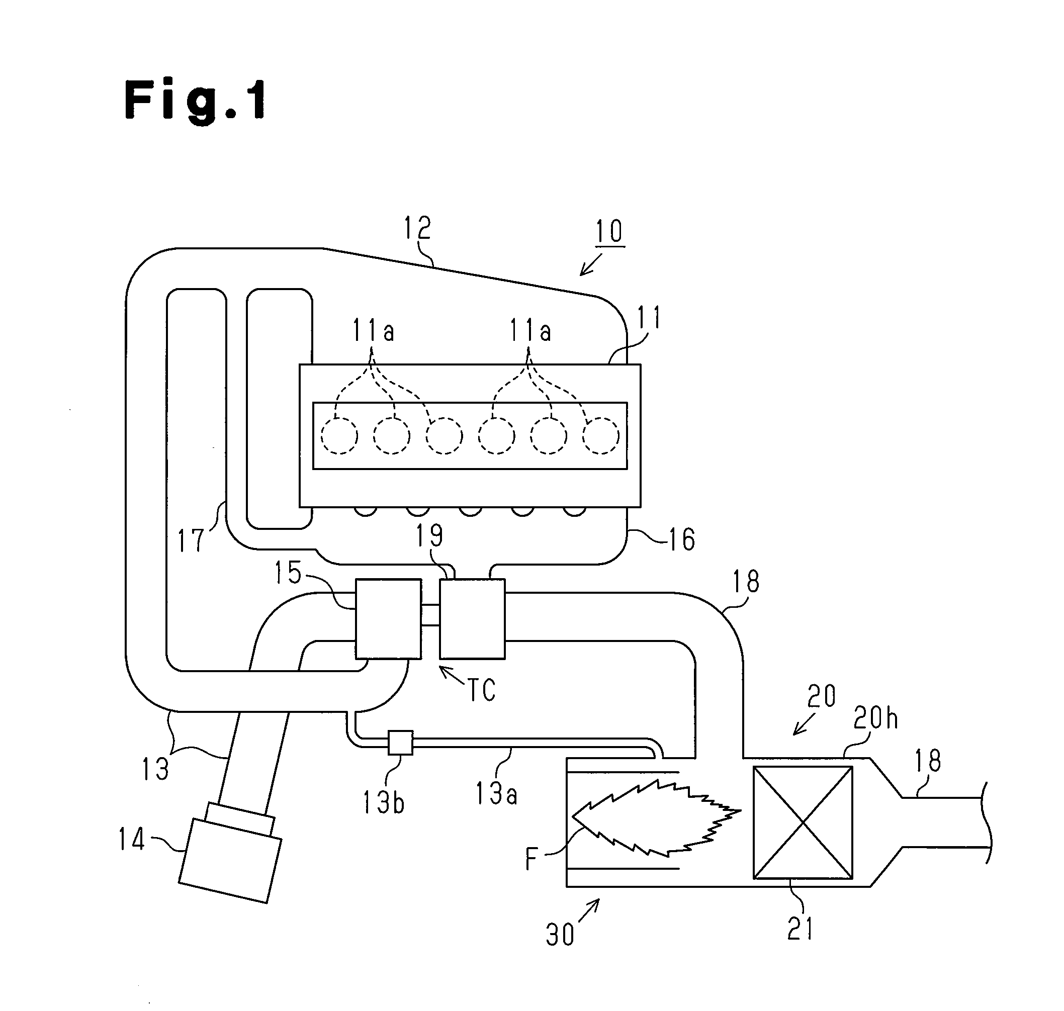
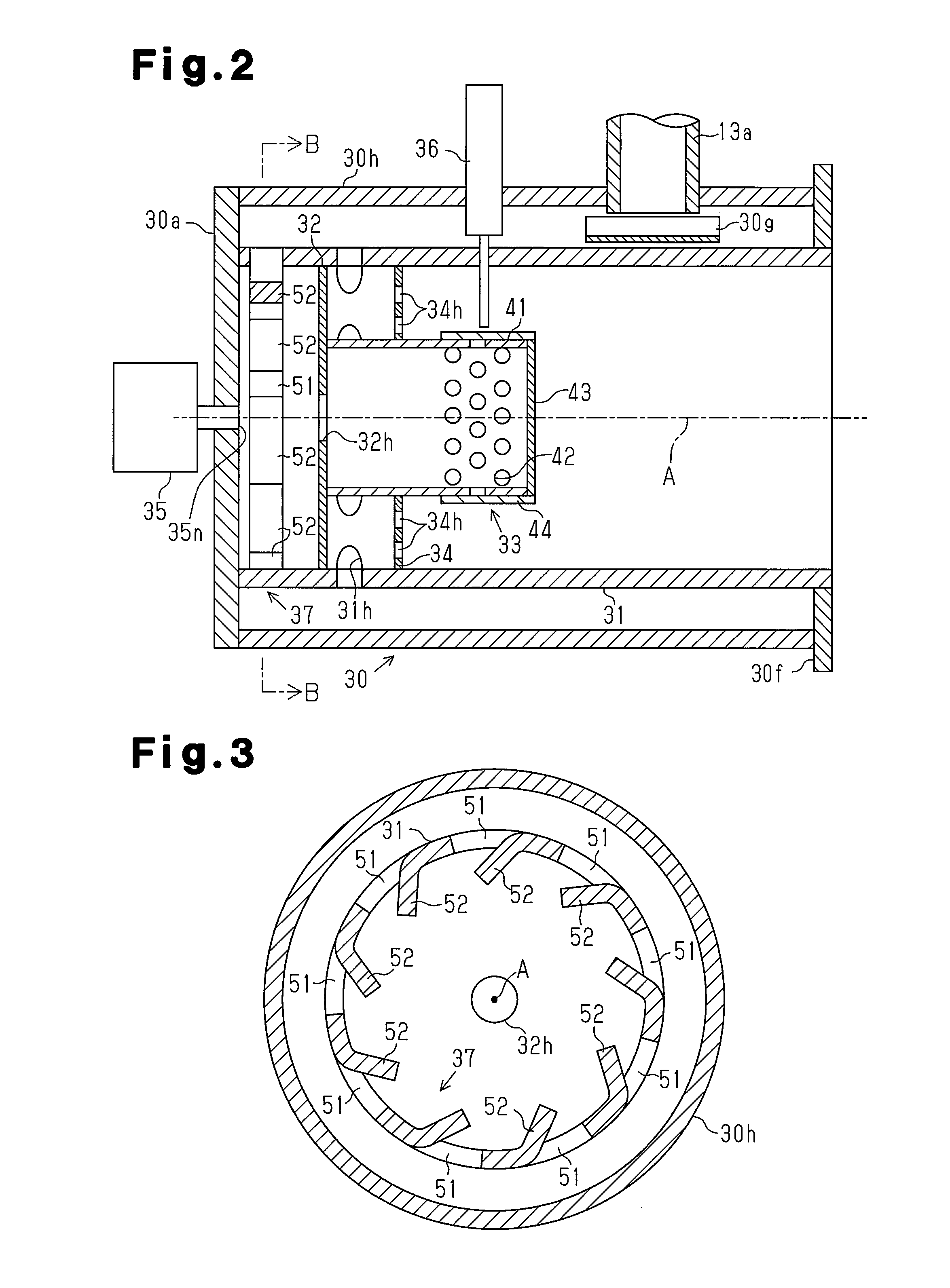
[0040]A first embodiment of a burner will be described with reference to FIGS. 1 to 4. The overall configuration of a diesel engine which is equipped with a burner will be described with reference to FIG. 1. A path of air taken into the diesel engine and a path of air discharged from the diesel engine will be mainly described here. Hereinafter, the intake air supply side is referred to as the upstream side with respect to the object to be explained, while the exhaust gas discharge side is referred to as the downstream side with respect to the object to be explained.

Schematic Configuration of Diesel Engine

[0041]As shown in FIG. 1, six cylinders 11a which are arranged in a row are formed at a cylinder block 11 of a diesel engine 10. An intake manifold 12 for supplying intake air to the cylinders 11a and an exhaust manifold 16 into which exhaust gas from the cylinders 11a flows are connected to the six cylinders 11a.

[0042]An air cleaner 14 is attached to an upstream end of an inlet pi...

second embodiment

[0081]A second embodiment of a burner will be described with reference to FIGS. 5 to 8. A burner according to the second embodiment is different from the burner according to the first embodiment and includes a member which produces a circulating flow in a space surrounded by the outer tube portion 31. Such differences will be described below in detail. The configuration of the burner and the operation of the burner will be described in this order.

Configuration of Burner

[0082]The configuration of the burner will be described with reference to FIG. 5. FIG. 5 is a cross-sectional view of the burner corresponding to FIG. 2 described in the first embodiment and that components equivalent to those in FIG. 2 are denoted by identical reference numerals.

[0083]As shown in FIG. 5, a substantially circular ring-shaped blow-off plate 38 is provided at an opening of a cylinder end closer to the DPF 21 of two end portions of a second tube portion 31. A discharge port 38h which extends through the ...


PUM

PropertyMeasurementUnit
timeaaaaaaaaaa
angleaaaaaaaaaa
shapeaaaaaaaaaa

Abstract

A burner includes a tubular inner tube portion and a tubular outer tube portion. The inner tube portion mixes fuel with air. The outer tube portion surrounds the inner tube portion. A peripheral wall of the inner tube portion has a gaseous mixture outflow hole. The gaseous mixture outflow hole causes a clearance between an inner peripheral surface of the outer tube portion and an outer peripheral surface of the inner tube portion to communicate with an interior of the inner tube portion. A peripheral wall of the outer tube portion has an air supplying hole. The air supplying hole further supplies air to the clearance.

Description

TECHNICAL FIELD[0001]The present disclosed technique relates to a burner including a tube portion which mixes fuel with air.BACKGROUND ART[0002]An engine exhaust gas purification apparatus which traps fine particles in exhaust gas with a diesel particulate filter (hereinafter referred to as a filter) has been widely used. In this exhaust gas purification apparatus, the function of the filter needs to be maintained by removing fine particles from the filter while the filter traps fine particles in exhaust gas to purify the exhaust gas. To this end, an exhaust gas purification apparatus including a burner which heats exhaust gas is proposed as described in patent document 1. In this exhaust gas purification apparatus, exhaust gas is heated through burning of fuel in the burner to raise the temperature of a filter to the extent that allows for soot, which is a major component of fine particles, to be removed. Removal of fine particles deposited on the filter recovers the function of th...

Claims


Application Information

Patent Timeline
Patent Type & Authority Applications(United States)
IPC IPC(8): F01N3/025F23D11/40F23D11/02F01N3/035B01F23/10
CPCF01N3/0253F23D11/02F23D11/408F01N3/035F01N3/025F01N3/20F23D11/10F23D11/40F23G7/06F23L1/00B01F23/10B01F25/20F01N3/30F01N3/36F01N3/38F01N2240/14F23D11/445F23G7/065F02B37/166F23D91/02Y02T10/12B01F23/12B01F25/103B01F2025/931B01F25/3131
Inventor TSUMAGARI, ICHIROSHIBUYA, RYOKOIDE, ATSUSHI
Owner HINO MOTORS LTD
Why Eureka
Try Eureka