
Transformer and Strobe Device

a technology of transformer and strobe, which is applied in the direction of instruments, low-pressure discharge lamps, optics, etc., can solve the problems of wax melting, leakage of coils, and increase of transformers,

Active Publication Date: 2015-07-23
NISSIN KOGYO CO LTD +1
View PDF4 Cites 5 Cited by
  • Summary
  • Abstract
  • Description
  • Claims
  • Application Information

AI Technical Summary

Benefits of technology

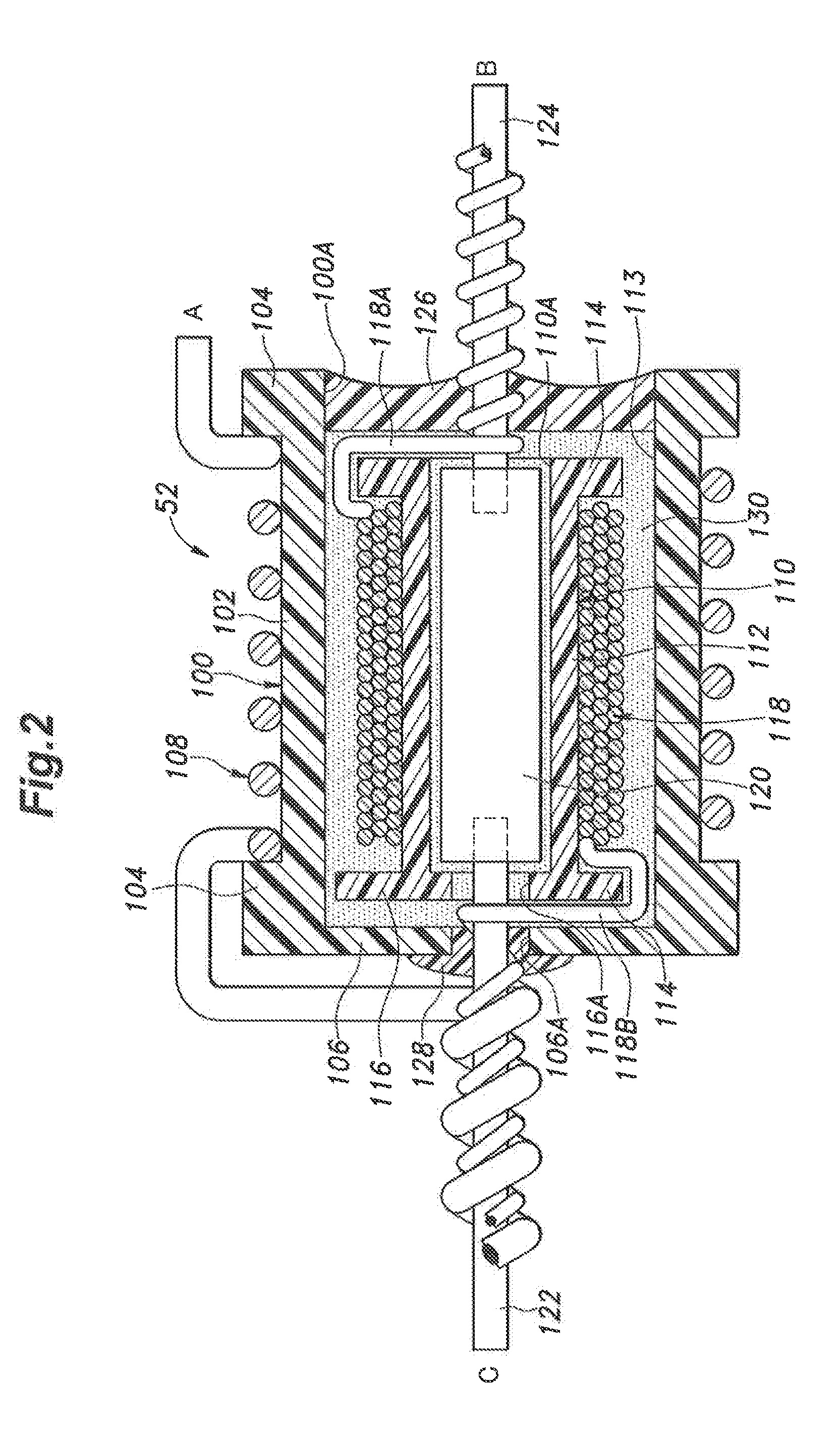
The present invention aims to prevent electrical short circuits and the loss of insulation between parts of the insulation-coated conductive wire of a transformer due to high temperatures. This is achieved by using a sealing member to form a sealed chamber that prevents leakage of the insulating wax and allows for easy and secure connection of the secondary winding to terminals. The patent also allows for separate winding processes for the primary and secondary windings, resulting in high productivity.

Problems solved by technology

However, if the light emission of the strobe device is repeated more than expected, for example, the load of the trigger transformer may increase and the temperature of the coils may become high to such a degree that the wax is melted and leaks from the coils, whereby the function of the wax of electrically insulating the coils may be lost.

Method used


Image

  • Transformer and Strobe Device
  • Transformer and Strobe Device
  • Transformer and Strobe Device

Examples


Embodiment Construction

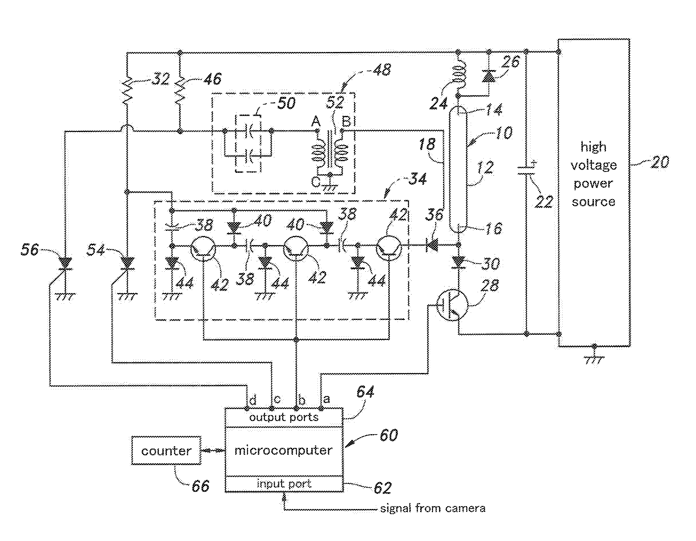
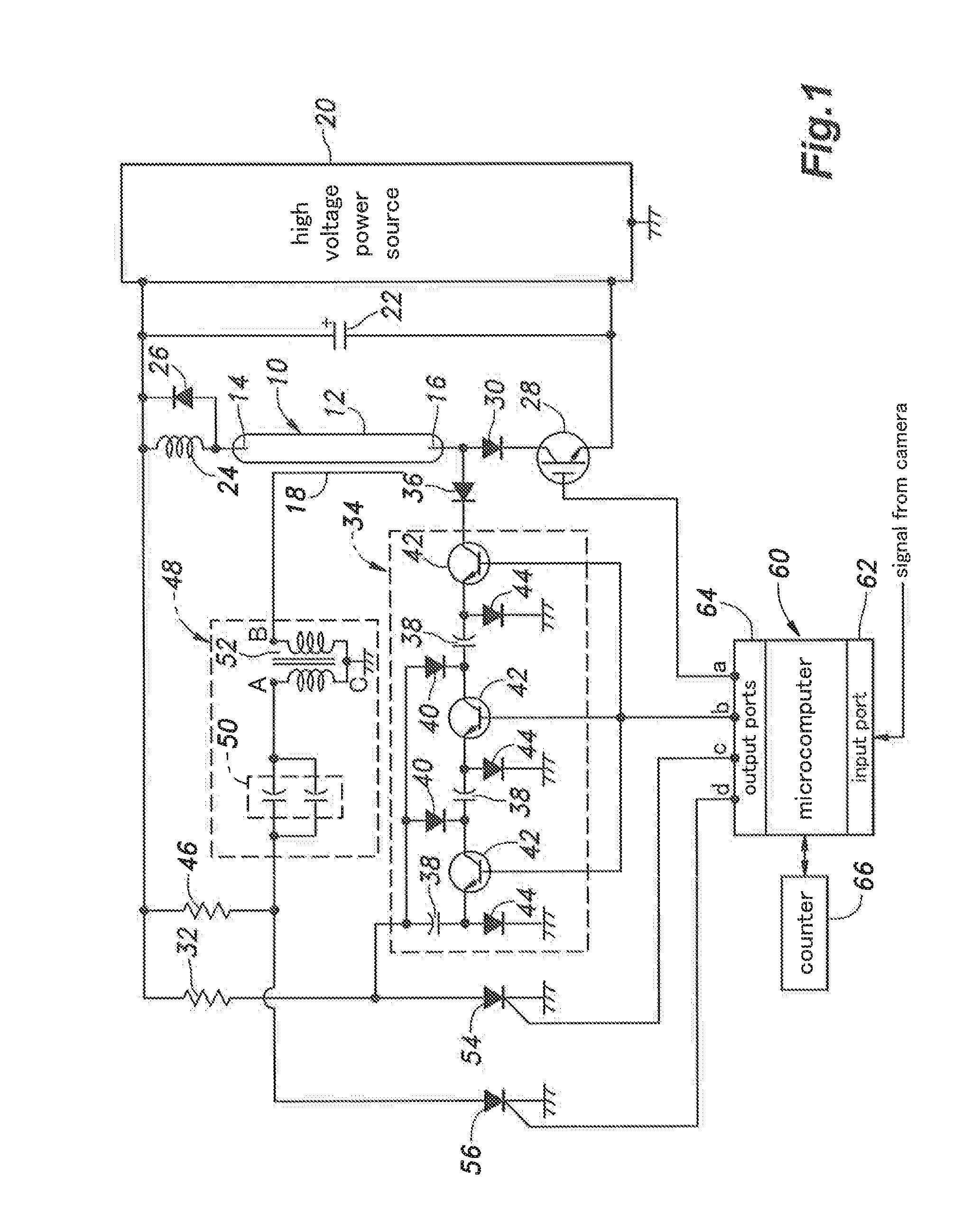
[0016]Now, an embodiment of a strobe device in which a transformer according to the present invention is employed as a trigger transformer of a trigger circuit will be described with reference to FIG. 1.

[0017]The strobe device according to the present embodiment includes a xenon discharge tube 10 as a flash discharge tube. The xenon discharge tube 10 includes an elongated glass tube 12, a pair of discharge electrodes 14 and 16 respectively serving as an anode and a cathode provided on either longitudinal end of the glass tube 12 and a trigger electrode 18 provided on the outside of an intermediate part of the glass tube 12, In order for the xenon discharge tube 10 to withstand the thermal stress caused by the repeated lighting of the xenon discharge tube 10 over a prolonged period of time, the glass tube 12 is made of quartz glass, and the electron emission material of the cathode includes barium.

[0018]The strobe device further includes a high voltage power source 20 which may have ...


PUM

PropertyMeasurementUnit
DC voltageaaaaaaaaaa
time delayaaaaaaaaaa

Abstract

To prevent a transformer such as a trigger transformer from becoming unable to perform transformation as designed due to short circuits caused by leakage of an insulating wax or the like even when the temperature of the transformer becomes high, a sealed chamber is formed in an outer bobbin which accommodates a secondary winding by a sealing member and the sealed chamber is filled with an insulating wax.

Description

TECHNICAL FIELD[0001]The present invention relates a transformer and a strobe device, and more specifically to a trigger transformer to be used in a trigger circuit of a strobe device.BACKGROUND ART[0002]A trigger transformer (transformer) to he used in a trigger circuit of a strobe device is known in which a secondary conductor (secondary coil) is formed around an outer circumference of a bobbin, a primary conductor (primary coil) is formed to surround the second conductor via an insulating film, and a core member is placed in the bobbin (see Patent Document 1, for example).BRIEF SUMMARY OF THE INVENTION[0003]In a case where the primary conductor and the secondary conductor are each constructed as a coil formed by winding an insulation-coated. conductive wire, in order to avoid the neighboring portions of the insulation-coated conductive wire from forming short circuits even if an insulating coating is peeled off from the insulation-coated conductive wire, it is considered to impre...

Claims


Application Information

Patent Timeline
Patent Type & Authority Applications(United States)
IPC IPC(8): H01F27/32H01J61/80G03B15/05H01F27/29H01J61/56
CPCH01F27/325H01F27/29H01J61/80G03B15/05H01J61/56H01F27/2828H01F27/324H01F2005/025
Inventor MAN, CHUN NIN
Owner NISSIN KOGYO CO LTD
Learn More