Dct based flicker detection

a flicker detection and dct technology, applied in the field of digital camera processing, can solve the problems of not all fluctuating light sources alternate at 50 hz or 60 hz frequency, not all flicker detection units can detect flicker, and various spatial and temporal artifacts of cameras with rolling shutters, so as to reduce or eliminate the effect of correct detection

Inactive Publication Date: 2015-07-23
NVIDIA CORP
View PDF3 Cites 21 Cited by
  • Summary
  • Abstract
  • Description
  • Claims
  • Application Information

AI Technical Summary

Benefits of technology

[0010]One advantage of the disclosed techniques is that the flicker resulting from fluctuating light sources is correctly detected and reduced or eliminated irrespectiv...

Problems solved by technology

One drawback of the above rolling shutter technique is that, because the different row subsets are exposed at different moments in time, cameras with rolling shutters suffer from various spatial and temporal artifacts such as camera movement, subject movement, skew, smear, and wobble.
One drawback of this possible solution is that not all fluctuating light sources alternate at a 5...

Method used


Image

  • Dct based flicker detection
  • Dct based flicker detection
  • Dct based flicker detection

Examples


Embodiment Construction

[0019]In the following description, numerous specific details are set forth to provide a more thorough understanding of the present invention. However, it will be apparent to one of skill in the art that the present invention may be practiced without one or more of these specific details.

System Overview

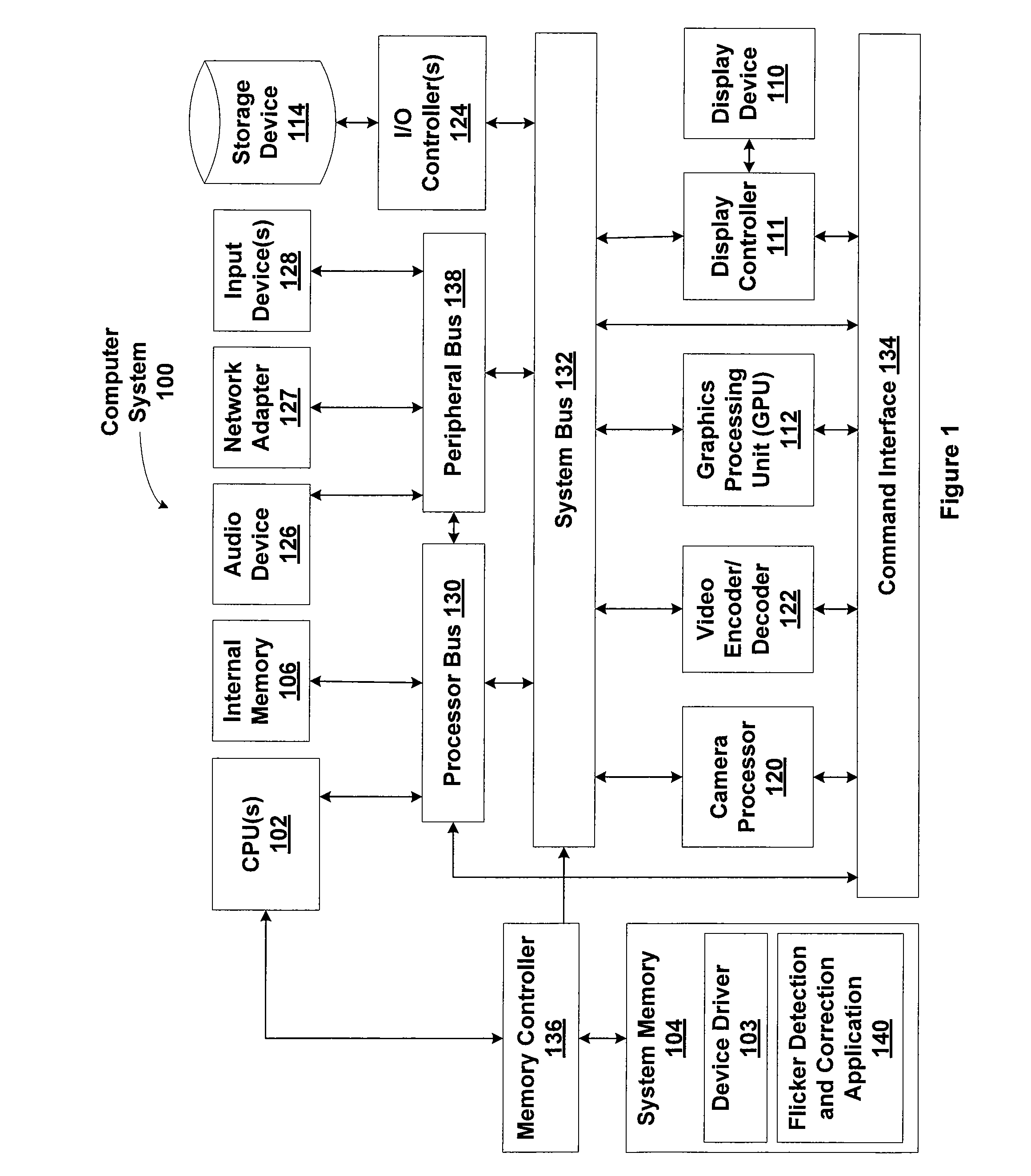
[0020]FIG. 1 is a block diagram illustrating a computer system 100 configured to implement one or more aspects of the present invention. As shown, computer system 100 includes, without limitation, one or more central processing units (CPUs) 102 coupled to a system memory 104 via a memory controller 136. The CPU(s) 102 may further be coupled to internal memory 106 via a processor bus 130. The internal memory 106 may include internal read-only memory (IROM) and / or internal random access memory (IRAM). Computer system 100 further includes a processor bus 130, a system bus 132, a command interface 134, and a peripheral bus 138. System bus 132 is coupled to a camera processor 120, video en...


PUM


Abstract

One embodiment of the present invention sets forth a technique for reducing flicker in image frames captured with a rolling shutter. A flicker detection and correction engine selects a first channel from a first image frame for processing. The flicker detection and correction engine subtracts each pixel value in the first channel from a corresponding pixel value in a prior image frame to generate a difference image frame. The flicker detection and correction engine identifies a first alternating current (AC) component based on a discrete cosine transform (DCT) associated with the difference image frame. The flicker detection and correction engine reduces flicker that is present in the first image frame based on the first AC component. One advantage of the disclosed techniques is that the flicker resulting from fluctuating light sources is correctly detected and reduced or eliminated irrespective of the frequency of the fluctuating light source.

Description

BACKGROUND OF THE INVENTION[0001]1. Field of the Invention[0002]Embodiments of the present invention generally relate to digital camera processing and, more specifically, to DCT-based flicker detection.[0003]2. Description of the Related Art[0004]Various handheld devices are widely available that provide the capability to capture photographs. These handheld devices include portable digital cameras as well as mobile devices with built-in cameras, such as smartphones and pad computers. These cameras typically employ a complementary metal-oxide-semiconductor (CMOS) sensors to capture light and convert the light into a digital signal that represents an image frame. Some cameras with CMOS sensors include a global shutter, where the entire CMOS sensor, corresponding to the entire image frame, is exposed at the same time. More typically, cameras with CMOS sensors include a rolling shutter, where a subset of rows of the CMOS sensor is exposed at any given time. An entire image frame is capt...

Claims


Application Information

Patent Timeline
IPC IPC(8): H04N5/235H04N5/217H04N5/353
CPCH04N5/2357H04N5/2173H04N5/3532H04N23/745H04N25/531
Inventor NGUYEN, HUGH PHUDENG, YININGDUJARDIN, ERIC FRANCOIS XAVIERSINHA, ABHINAV
Owner NVIDIA CORP
Why Eureka
Try Eureka