Method for Monitoring and Controlling Drilling Fluids Process

a technology of drilling fluid and process, applied in the direction of survey, instruments, borehole/well accessories, etc., can solve the problems of limited methodologies and still a substantial gap in time between

Inactive Publication Date: 2015-07-30
ONSITE INTEGRATED SERVICES
View PDF8 Cites 44 Cited by
  • Summary
  • Abstract
  • Description
  • Claims
  • Application Information

AI Technical Summary

Benefits of technology

[0008]The present invention relates generally to methods for characterizing a process fluid by in-process measurements that allow for continuously obtaining information regarding relative and actual amounts of various components thereof. Various embodiments comprise continuously quantifying the amounts of water and non-aqueous liquids (e.g., oil) in a mud, as well as the salt anion content of a mud. Various embodiments comprise determining and / or calculating the amount of various mud characteristics, such as solids, salinity, and oil / water ratio, in substantially real time. The present invention also relates generally to methods for utilizing continuously obtained downhole information to identify and monitor then present, undesired downhole drilling phenomena and control drilling operations based on such identification, and methods for utilizing continuously obtained downhole information to identify and monitor potential, undesired downhole drilling phenomena and control drilling operations based on such identification.

Problems solved by technology

Even if samples are collected and analyzed more frequently, there is still a substantial gap in time between the when the mud characteristics are present in the drilling operation, (i.e., when the sample is obtained), and when the laboratory testing results are available.
These methodologies are, however, limited by mud characteristic information obtainable thereby.

Method used


Image

  • Method for Monitoring and Controlling Drilling Fluids Process
  • Method for Monitoring and Controlling Drilling Fluids Process
  • Method for Monitoring and Controlling Drilling Fluids Process

Examples


Embodiment Construction

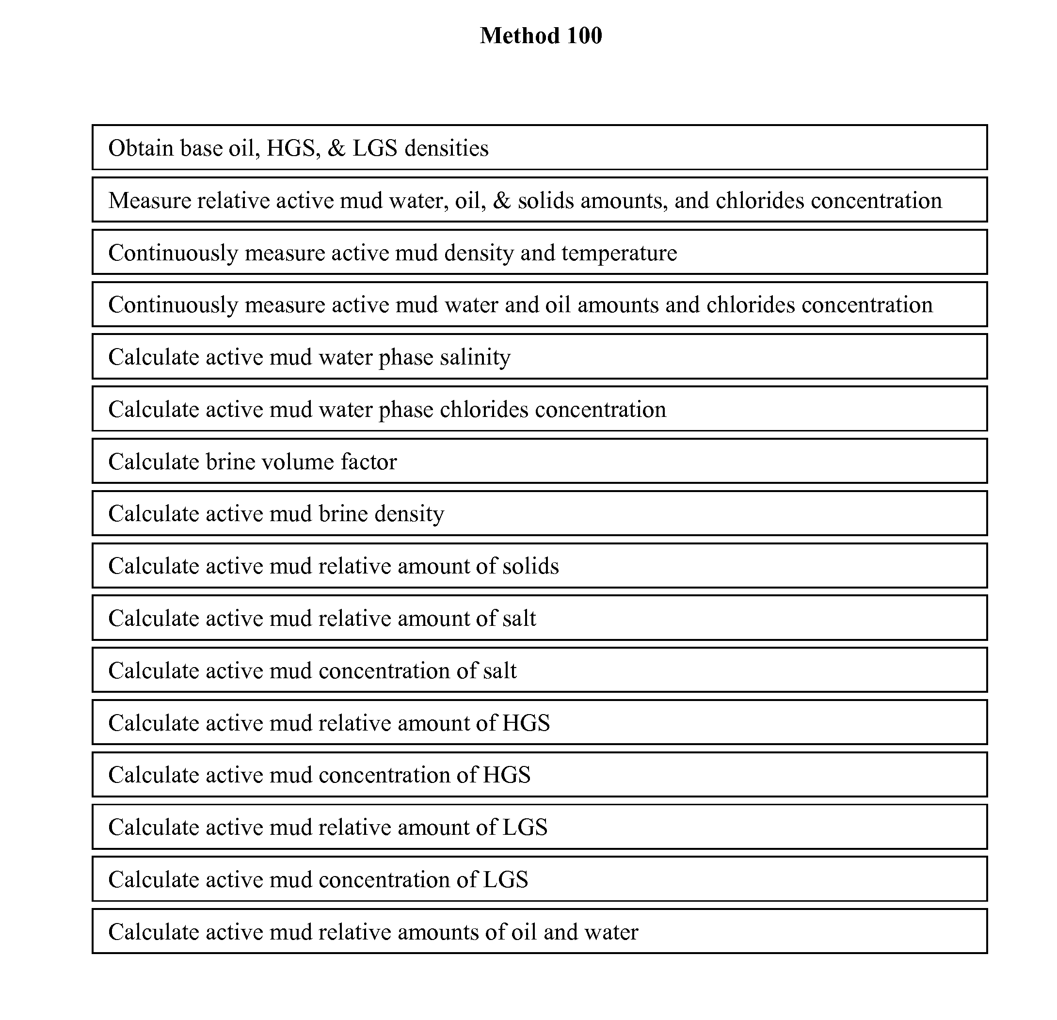
[0011]During a drilling operation, the drilling mud may comprise water, one or more oil-based drilling fluids and / or one or more synthetic drilling fluids, salts (e.g., calcium chloride (CaCl2)), minerals (e.g., barite), viscosifiers, emulsifiers, wetting agents, additional chemical or biological additives, and drill cuttings. Thus, a mud may therefore comprise a slurry of fluid and insoluble materials suspended or otherwise entrained therein. While embodiments of the method described herein are generally applicable to fluids, certain embodiments may refer specifically to mud. Such reference is merely exemplary and not limiting in terms of the applicability of embodiments of the present invention to other fluids or fluid / solid mixtures. Fluids to which embodiments of the present invention may be employed may comprise an oil / water emulsion or a water / oil emulsion. In addition, fluids employable in embodiments of the present invention may comprise various salts or mixture of salts. Ty...


PUM


Abstract

A method for continuously determining characteristics of a process fluid includes inline real-time analysis. In one embodiment, inline analysis of water, oil, and salt anions provides continuously obtained measurements for determination of various drilling fluid properties and assessment of drilling operation parameters and wellbore conditions. In one embodiment, the continuously provided measurements and/or data calculated therefrom allow for monitoring and controlling of a downhole drilling operation. In embodiments of the method, automated control of drilling operations using the continuously generated information can be accomplished. In one embodiment, a material balance of drilling fluid components using the continuously generated information is provided.

Description

CROSS-REFERENCE TO RELATED APPLICATIONS[0001]This application claims the benefit of U.S. Provisional Application No. 61 / 965,260, entitled “Utilize flow rate, density, salinity and water cut inline instrumentation to optimize the drilling fluids process,” filed on Jan. 27, 2014, which application is incorporated herein by reference as if reproduced in full below.STATEMENT REGARDING FEDERALLY SPONSORED RESEARCH OR DEVELOPMENT[0002]Not Applicable.BACKGROUND OF THE INVENTION[0003]1. Field of the Invention[0004]Oil and gas well drilling operations typically involve the use of a drilling fluid slurry, also sometimes referred to as “mud.” Mud may contain aqueous and non-aqueous components and form emulsions thereof. Typically present in the mud during drilling operations are (water and / or oil) insoluble materials (“solids”), such as salts (e.g., calcium chloride), minerals (e.g., barite), additives, and drill cuttings. Determination of the amounts and / or relative concentrations of the vari...

Claims


Application Information

Patent Timeline
Patent Type & Authority Applications(United States)
IPC IPC(8): E21B44/00E21B49/00G05B15/02E21B49/08
CPCE21B44/00G05B15/02E21B49/003E21B49/08E21B47/10E21B21/00
Inventor NORMAN, JASON BRIANLOTT, WILLIAM GERALD
Owner ONSITE INTEGRATED SERVICES
Why Eureka
Try Eureka