Rotation position detection device and air conditioner

Active Publication Date: 2015-07-30
DAIKIN IND LTD
View PDF2 Cites 3 Cited by
  • Summary
  • Abstract
  • Description
  • Claims
  • Application Information

AI Technical Summary

Benefits of technology

[0029]According to the first aspect of the device for detecting rotation position (4) relating to the present disclosure, because a rotation position is determined when the first line induced voltage and the second line induced voltage match each other, even when an offset has occurred in common in the first line induced voltage and the second line induced voltage, the switching point in time does not vary. Accordingly, estimation accuracy of a rotation position can be enhanced.
[0030]According to the second aspect of the device for detecting rotation position relating to the present disclosure, as compared with the case of detecting an induced voltage of the AC line, extracting the induced voltage of the minimum phase from the detected induced voltage, and calculating the line induced voltage by subtracting the induced voltage of the minimum phase from the induced voltage, the first line induced voltage and the second line induced voltage can be easily obtained (that is, without a computation).
[0031]According to the third aspect of the device for detecting rotation position relating to the present disclosure, the first voltage and the second voltage smaller than the first line induced voltage and the second line ind

Problems solved by technology

Therefore, detection accuracy of

Method used


Image

  • Rotation position detection device and air conditioner
  • Rotation position detection device and air conditioner
  • Rotation position detection device and air conditioner

Examples


first embodiment

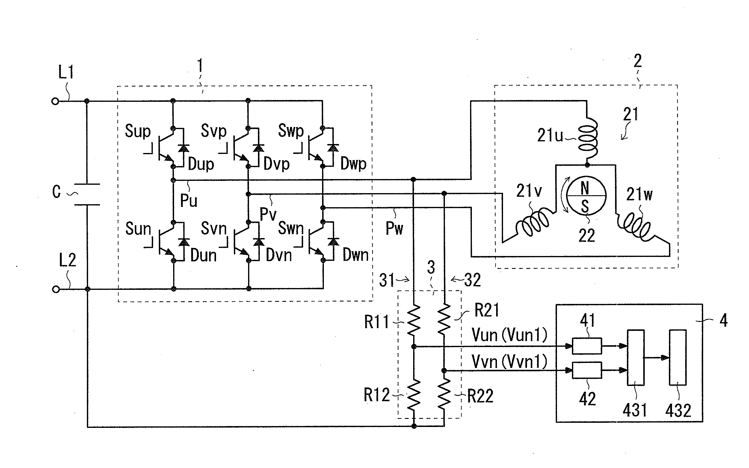
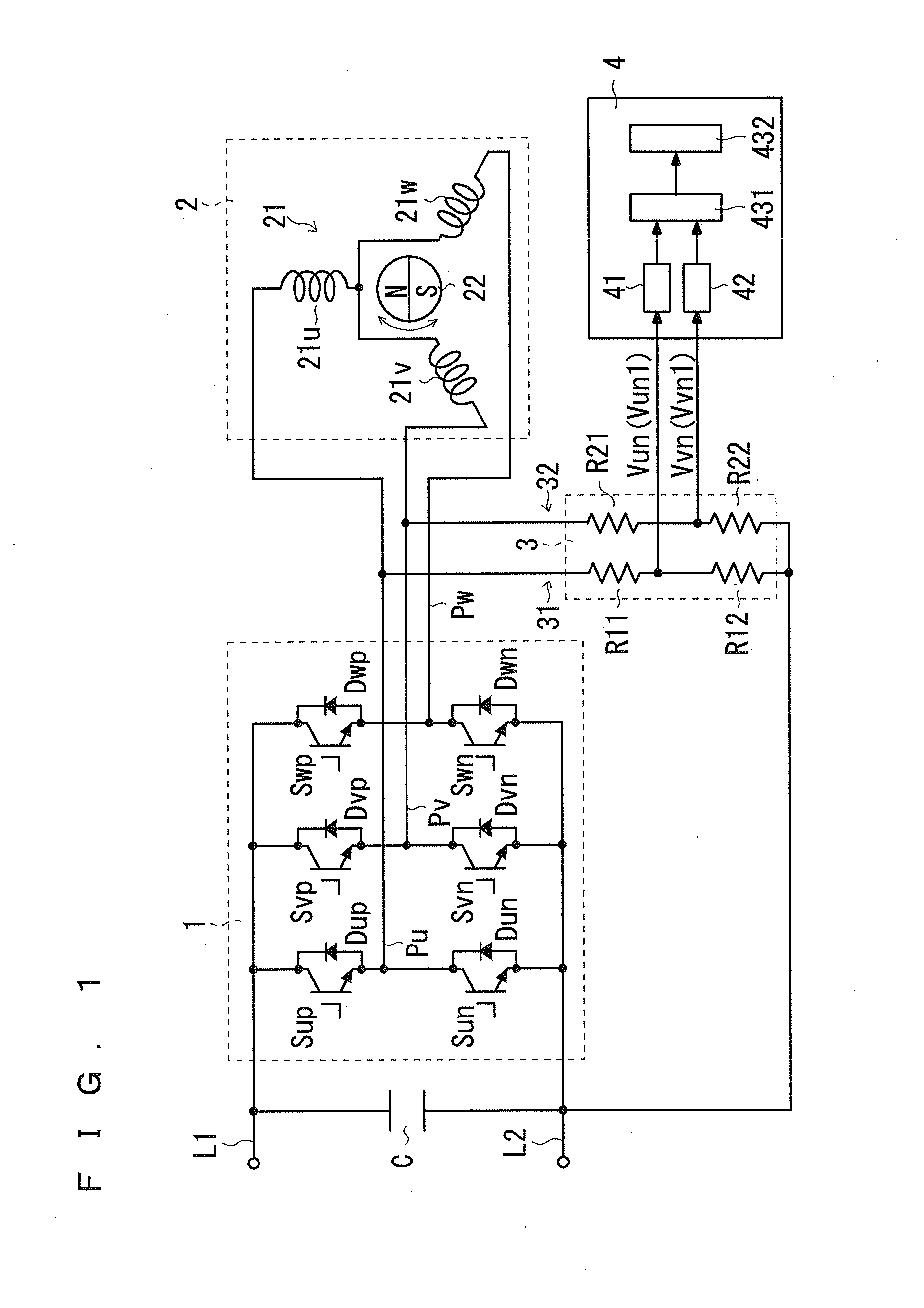
[0068]As shown in FIG. 1, the present motor control device includes a power converter 1, a motor 2, and a rotation position detector 4.

[0069]The power converter 1 is connected to DC lines L1 and L2 at an input side thereof, and is connected to AC lines Pu, Pv, and Pw at an output side thereof. Between the DC lines L1 and L2, a DC voltage is applied. This DC voltage is applied by a converter not shown, for example. This converter converts an AC voltage from a commercial AC power supply, for example, to a DC voltage, and applies this to between the DC lines L1 and L2. As such a converter, a diode rectification circuit formed by a diode bridge, for example, can be employed. For the voltage of the commercial AC power supply, any one of 100V, 200V, 220V, and 400V can be employed, for example. In the case where the commercial AC power supply outputs a single-phase AC voltage, the DC voltage is √2 of the voltage of the commercial AC power supply, and becomes 141V, 283V, 311V, and 566V resp...

second embodiment

[0117]In the second embodiment, the voltage detector 3 includes a detection-voltage limiting unit that limits the detection voltage to a predetermined value, when the line induced voltages Vun and Vvn are equal to or greater than a predetermined reference value.

[0118]For example, as shown in FIG. 9, the voltage detector 3 further includes a protection circuit 33 as compared with the voltage detector 3 in FIG. 1. The protection circuit 33 which is an example of the detection-voltage limiting unit outputs a voltage of a predetermined value to the rotation position detector 4 when the line induced voltages Vun and Vvn are equal to or greater than the reference value. That is, the protection circuit 33 avoids application of a voltage exceeding the predetermined value (hereinafter, also referred to as upper limit value) to the rotation position detector 4. Accordingly, the protection circuit 33 can protect the rotation position detector 4 from an excess voltage.

[0119]The protection circu...

third embodiment

[0143]In the third embodiment, the rotation direction can be specified. As a point different from the first embodiment, the present motor driving device is further provided with a rotation-direction specifying unit 5 shown in FIG. 14. The rotation-direction specifying unit 5 receives from the detector 431 that the line induced voltages match each other, and further receives at least one of the line induced voltages Vun and Vvn.

[0144]The rotation-direction specifying unit 5 specifies a rotation direction as a predetermined direction based on at least one of values of the line induced voltages Vun and Vvn when the line induced voltages Vun and Vvn match each other. This will be described in detail.

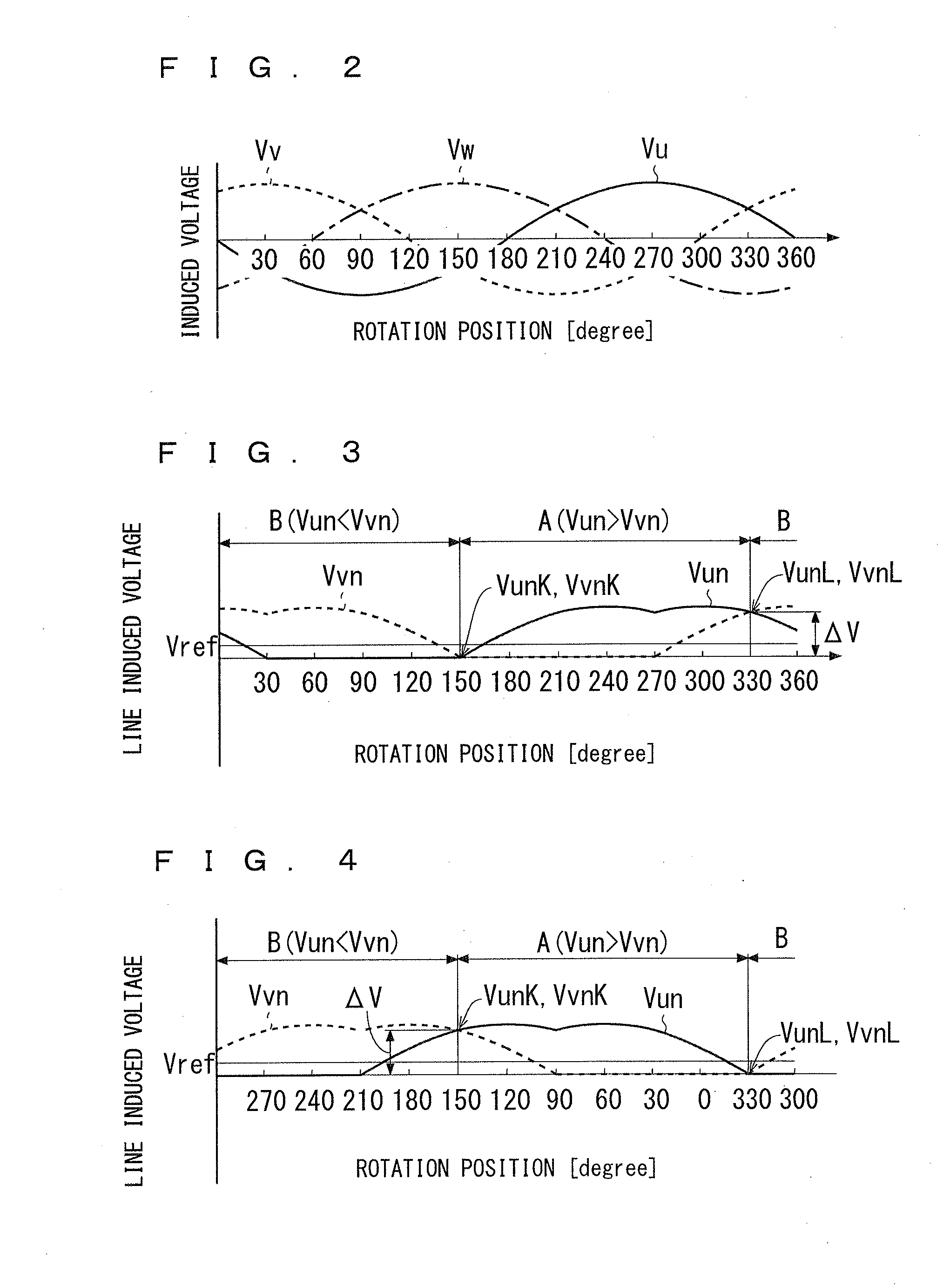
[0145]As shown in FIG. 3, in the forward rotation direction, the line induced voltages Vun and Vvn when the line induced voltage Vun exceeds the line induced voltage Vvn (when the rotation position is 150 degrees) take a relatively small value (for example, zero). Hereinafter, the line induc...


PUM


Abstract

A detector detects whether or not a first line induced voltage and a second line induced voltage match each other, the first line induced voltage being a potential difference of a first phase potential of phase potentials relative to a reference potential, and the second line induced voltage being a potential difference of a second phase potential of the phase potentials other than the first phase potential relative to the reference potential. The phase potentials is outputted by the armature due to an induced electromotive force. The reference potential is any one of a minimum phase and a maximum phase. A rotation-position setting unit sets, to a predetermined value, an estimation value of a rotation position of the motor 2 at a point in time when the first line induced voltage and the second line induced voltage match each other.

Description

TECHNICAL FIELD[0001]The present disclosure relates to a device for detecting a rotation position and an air conditioner, and particularly relates to a motor control device that controls a motor having a permanent magnet.BACKGROUND ART[0002]In Japanese Patent Application Laid-Open No. 2010-233390 an inverter that drives a permanent-magnet synchronous motor is described, and a rotation position of the motor is detected based on a line voltage of the motor. In Japanese Patent Application Laid-Open No. 2010-233390, phase voltages are detected, and a line voltage is calculated based on these phase voltages. Then, by detecting a zero-crossing point of these line voltages, a rotation position of the motor is determined to a position corresponding to the zero-crossing point.[0003]Further, as techniques relevant to the present disclosure, Japanese Patent Application Laid-Open No. 2011-19348 and Japanese Patent No. 2609840 are disclosed.SUMMARYProblems to be Solved[0004]In order to detect a ...

Claims


Application Information

Patent Timeline
IPC IPC(8): G01D5/20F04D15/00H02P6/06H02P6/18H02P6/08H02P6/17H02P6/182
CPCF04D15/0094G01D5/20H02P6/188H02P23/14H02P2207/05H02P6/18H02K29/00F24F13/08F04B49/10F04D27/001F04B49/06F04D15/0077F04D15/0088
Inventor HIBINO, HIROSHI
Owner DAIKIN IND LTD
Why Eureka
Try Eureka