
Endoscope system, processor device for endoscope system, operation method for endoscope system, and operation method for processor device

a processor device and endoscope technology, applied in the field of endoscope system, can solve the problems of low robustness against the movement of the observation target or the endoscope, degrade the calculation accuracy of oxygen saturation, etc., and achieve the effect of accurate calculation of oxygen saturation and increased robustness against movemen

Active Publication Date: 2015-08-06
FUJIFILM CORP
View PDF0 Cites 18 Cited by
  • Summary
  • Abstract
  • Description
  • Claims
  • Application Information

AI Technical Summary

Benefits of technology

The invention provides an endoscope system that is able to accurately calculate oxygen saturation even if there is movement of the observation target or endoscope. This is achieved by increasing the robustness against movement by including a position shift and changes in the light amount ratio between frames. This allows for more accurate and reliable data to be collected during endoscopy procedures.

Problems solved by technology

The position shift or the change in the light amount ratio degrades the calculation accuracy of the oxygen saturation.
That is, robustness against the movement of the observation target or the endoscope is low.

Method used


Image

  • Endoscope system, processor device for endoscope system, operation method for endoscope system, and operation method for processor device
  • Endoscope system, processor device for endoscope system, operation method for endoscope system, and operation method for processor device
  • Endoscope system, processor device for endoscope system, operation method for endoscope system, and operation method for processor device

Examples


first embodiment

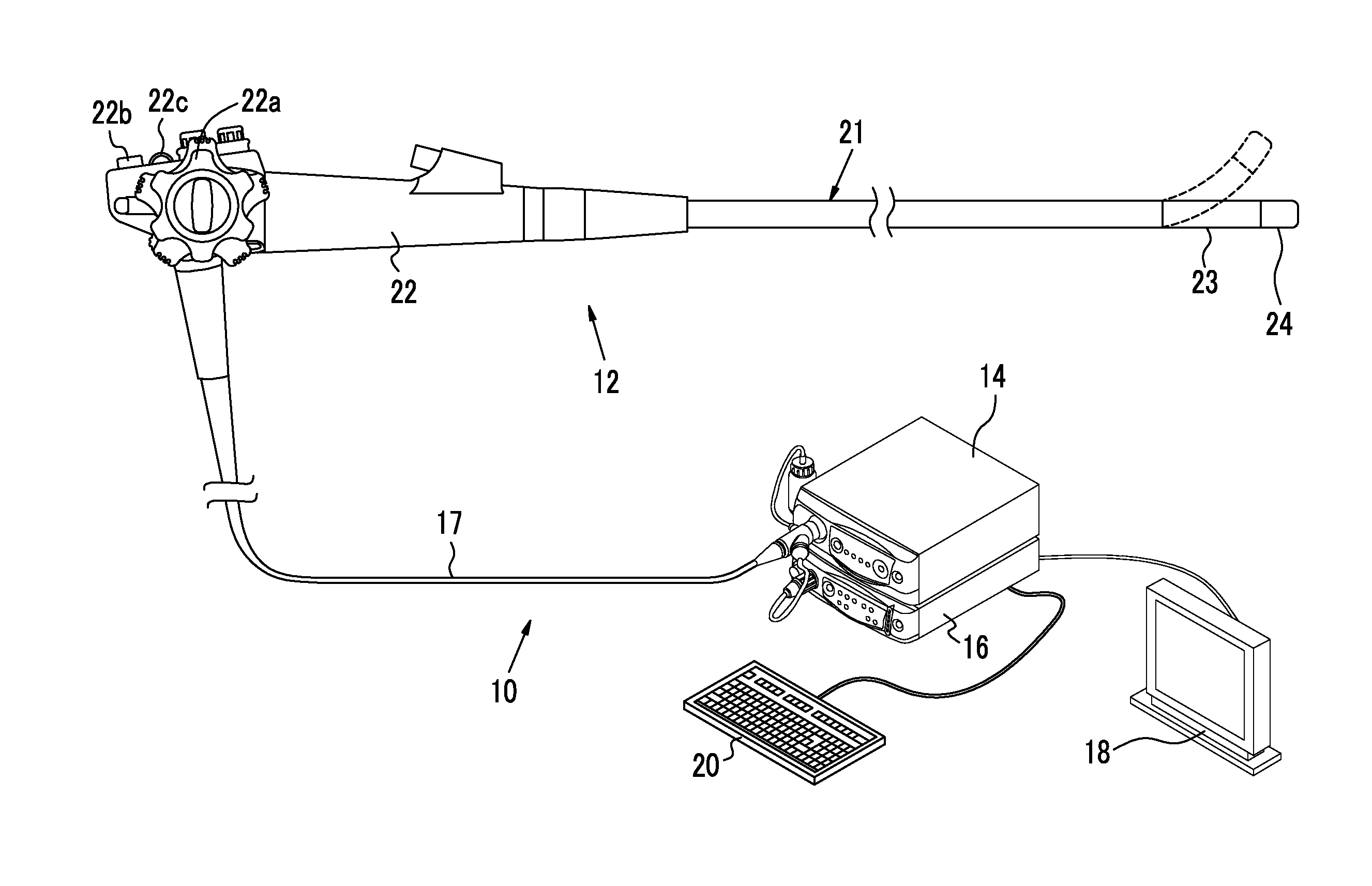
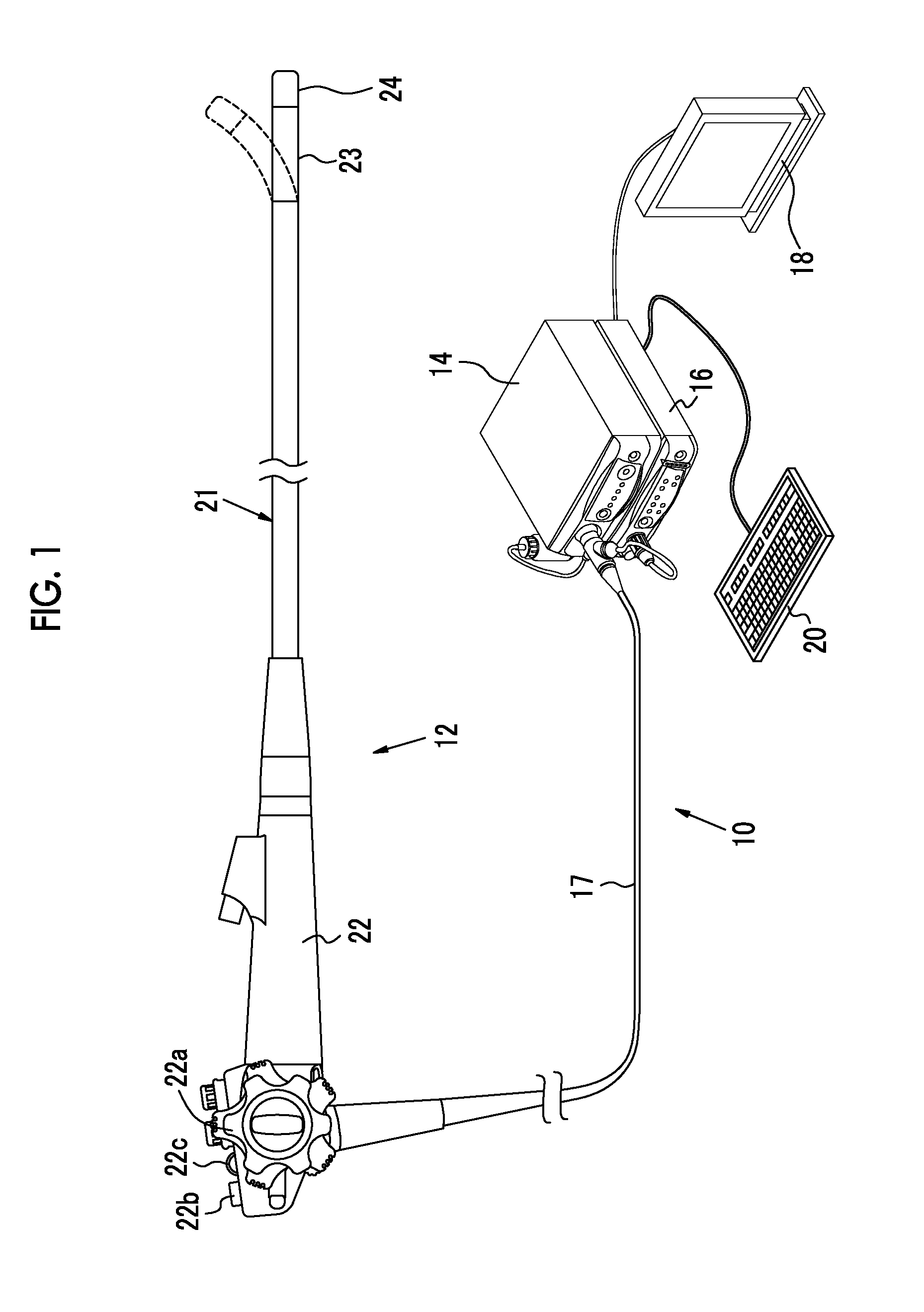
[0049]As shown in FIG. 1, an endoscope system 10 according to a first embodiment includes an endoscope 12, a light source device 14, a processor device 16, a monitor 18 (display unit), and a console 20. The endoscope 12 is optically connected to the light source device 14, and is electrically connected to the processor device 16. The endoscope 12 includes an inserted portion 21 that is inserted into a subject, an operating portion 22 provided at the base end of the inserted portion 21, and a bending portion 23 and a distal portion 24 that are provided at the distal side of the inserted portion 21. By operating an angle knob 22a of the operating portion 22, the bending portion 23 is bent. The distal portion 24 can be directed in a desired direction by the bending operation.

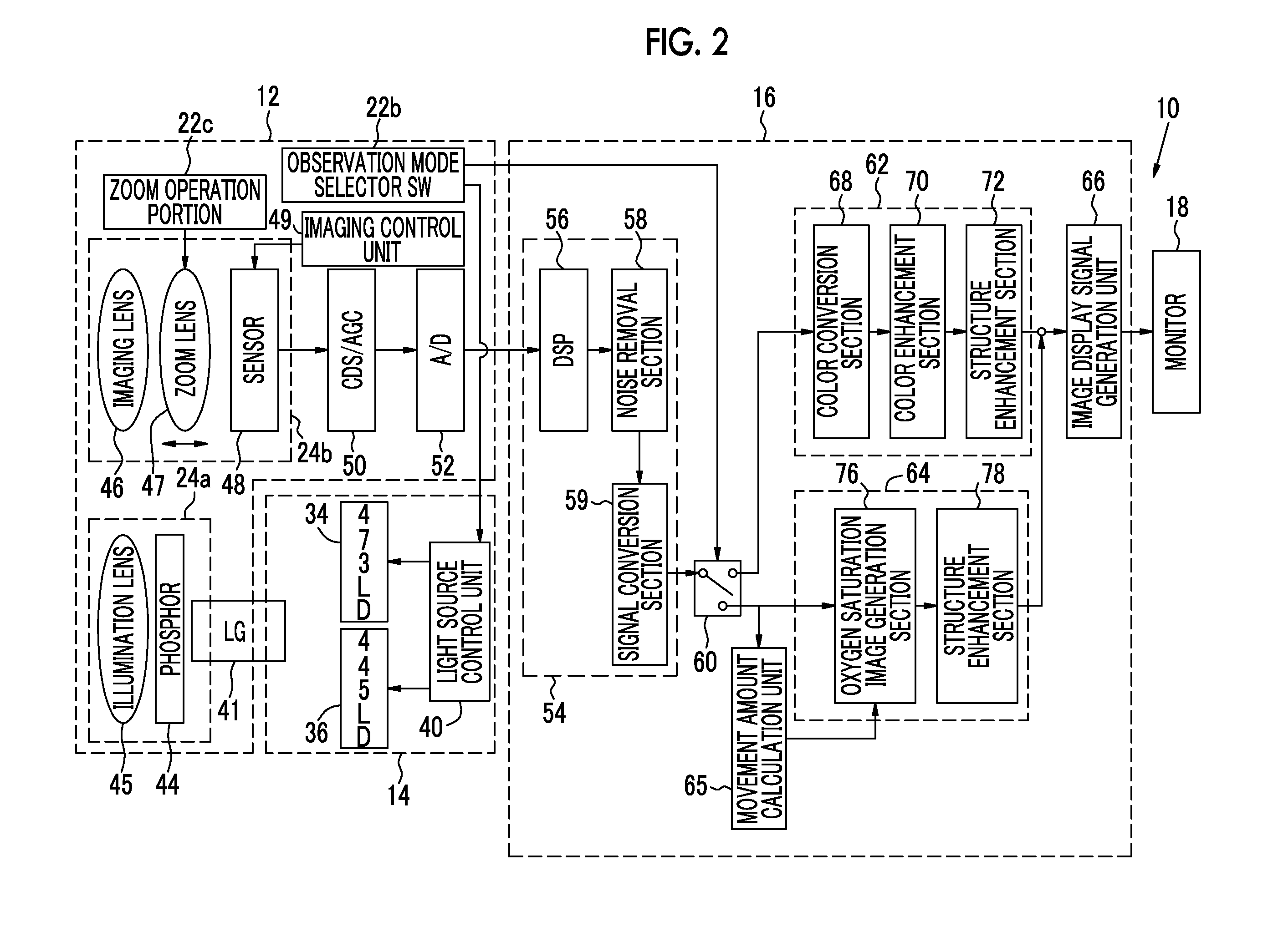
[0050]In addition to the angle knob 22a, an observation mode selector SW (observation mode selector switch) 22b, a zoom operation portion 22c, and a freeze button (not shown) for saving a still image are provided i...

second embodiment

[0103]An endoscope system according to a second embodiment is formed by replacing the movement amount calculation unit 65 and the mode switching section 80, the signal ratio calculation section 81, and the oxygen saturation calculation section 83 of the oxygen saturation image generation section 76 in the first embodiment with a movement amount calculation unit 265, a mode switching section 280, a signal ratio calculation section 281, and an oxygen saturation calculation section 283 shown in FIG. 13. Other configurations are the same as the endoscope system 10 according to the first embodiment.

[0104]The movement amount calculation unit 265 is the same as the movement amount calculation unit 65 of the first embodiment in that an image signal is acquired from the image processing switching unit 60 and the movement amount is calculated using the acquired image signal when the observation mode selector SW 22b is set to the special observation mode and the same method is used. However, t...

third embodiment

[0111]An endoscope system according to a third embodiment is formed by replacing the signal ratio calculation section 81, the oxygen saturation calculation section 83, and the image generation section 84 of the first embodiment with a signal ratio calculation section 381, an oxygen saturation calculation section 383, and an image generation section 384 shown in FIG. 15. In the endoscope system according to the third embodiment, the mode switching section 80 is not provided, and the movement amount calculated by the movement amount calculation unit 65 is input to the image generation section 384. Other configurations are the same as that of the endoscope system 10 according to the first embodiment.

[0112]The signal ratio calculation section 381 includes a first mode signal ratio calculation section 381A and a second mode signal ratio calculation section 381B. The first mode signal ratio calculation section 381A calculates the signal ratios B1 / G2 and R2 / G2 in the first mode, and the se...


PUM


Abstract

An endoscope system includes: a phosphor and first and second blue laser light sources that emit first white light and second white light having different emission spectrums; a sensor that images an observation target under illumination with the first white light and outputs a first image signal and images the observation target under illumination with the second white light and outputs a second image signal; a movement amount calculation unit that calculates the movement amount of the observation target based on the first or second image signal; and an oxygen saturation calculation unit that calculates the oxygen saturation based on the movement amount in at least one of a first mode, in which the oxygen saturation is calculated using the first and second image signals, and a second mode, in which the oxygen saturation is calculated using the first image signal.

Description

CROSS-REFERENCE TO RELATED APPLICATIONS[0001]The present application claims priority under 35 U.S.C. §119 to Japanese Patent Application No. 2014-21779, filed on Feb. 6, 2014, all of which are hereby expressly incorporated by reference into the present application.BACKGROUND OF THE INVENTION[0002]1. Field of the Invention[0003]The present invention relates to an endoscope system, a processor device for an endoscope system, an operation method for an endoscope system, and an operation method for a processor device for calculating biological function information regarding the oxygen saturation of blood hemoglobin from an image signal obtained by imaging an observation target in a subject.[0004]2. Description of the Related Art[0005]In the medical field, it is common to perform diagnosis using an endoscope system including a light source device, an endoscope, and a processor device. In recent years, diagnosis of a lesion using the oxygen saturation of blood hemoglobin in biological fun...

Claims


Application Information

Patent Timeline
Patent Type & Authority Applications(United States)
IPC IPC(8): A61B5/1455A61B1/00A61B5/00A61B1/05A61B1/06A61B5/1459
CPCA61B5/14552G06T2207/30004A61B5/1459A61B5/7207A61B1/05A61B1/00045A61B1/00009A61B1/04A61B1/063A61B1/0646A61B1/0653A61B1/0669A61B5/145A61B5/1455A61B5/489G06T7/0012G06T2207/10068G06T2207/10152A61B1/0638G06T7/0014G06T2207/10024G06T2207/20021G06T2207/30096A61B1/000094A61B1/044
Inventor SHIGETA, NORIMASA
Owner FUJIFILM CORP
Learn More