Testing system for drivetrain

Active Publication Date: 2015-08-06
MEIDENSHA ELECTRIC MFG CO LTD
View PDF8 Cites 36 Cited by
  • Summary
  • Abstract
  • Description
  • Claims
  • Application Information

AI Technical Summary

Benefits of technology

[0030]According to the present invention, it is possible to easily simulate various running states ranging f

Problems solved by technology

The tires are likely to slip on a slippery road surface such as a snowy or icy surface that actually exists; however, the tes

Method used


Image

  • Testing system for drivetrain
  • Testing system for drivetrain
  • Testing system for drivetrain

Examples


first embodiment

[0049]A drive-train test system 1 according to a first embodiment of the present invention is described with reference to the accompanying drawings.

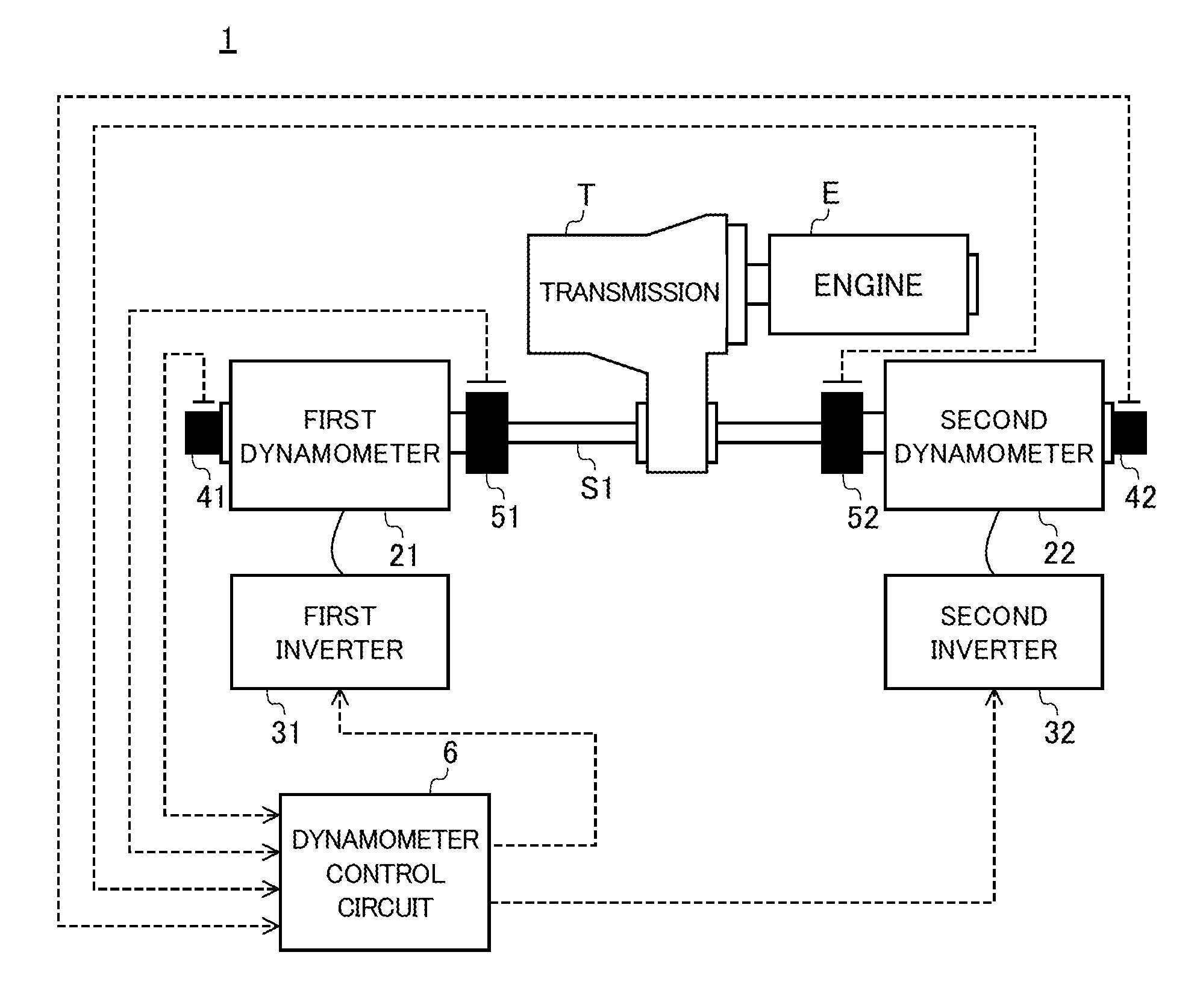
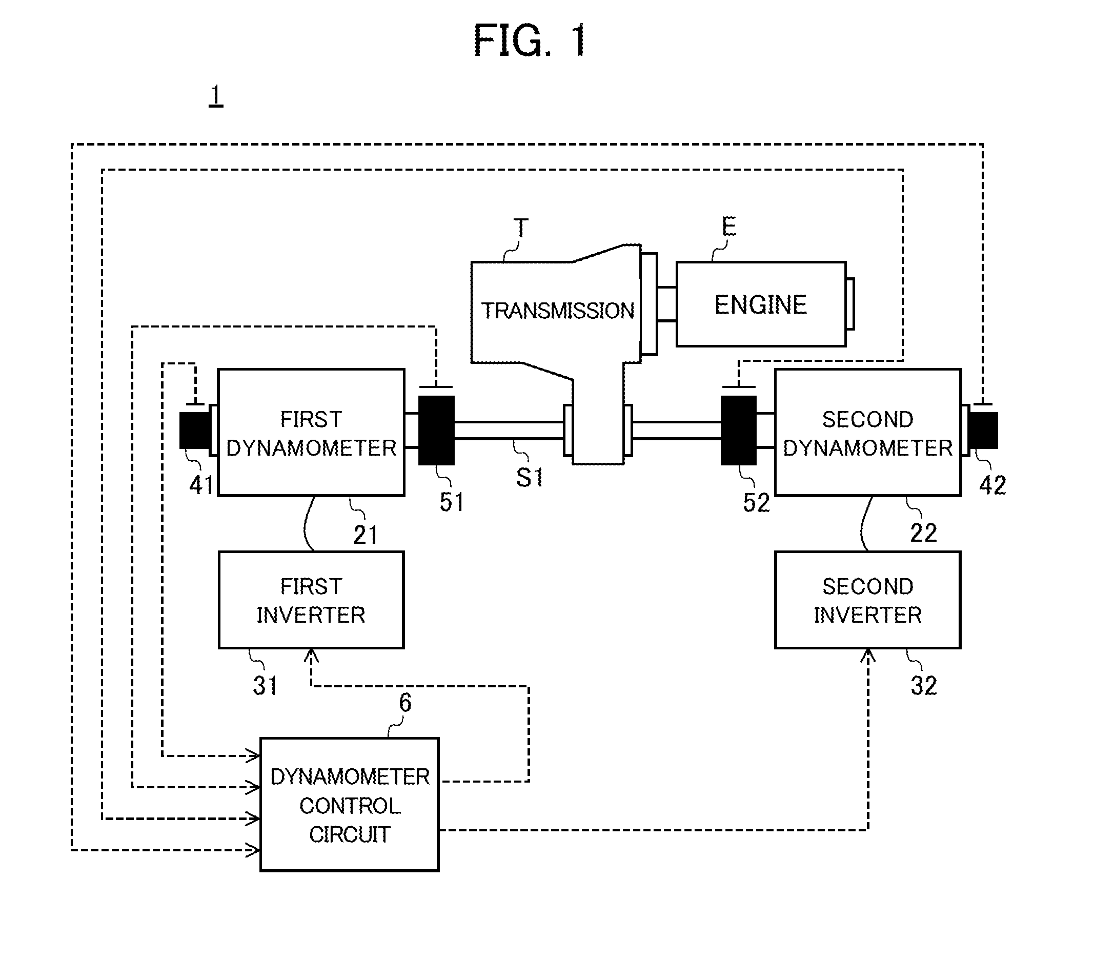
[0050]FIG. 1 is a schematic diagram showing a configuration of the test system 1 of the present embodiment. FIG. 1 shows an example of the test system 1, of which test pieces are a transmission T of an FF-drive vehicle, and an engine E connected to an input shaft thereof; however, the present invention is not limited thereto. The test piece may be a transmission and an engine of an FR-drive vehicle. A power source connected to the input shaft of the transmission T may be a dynamometer in place of the real engine E.

[0051]The test system 1 is provided with: a first dynamometer 21 and a second dynamometer 22, which are connected to two end sides of an output shaft S1 of the transmission T; a first inverter 31 and a second inverter 32 for supplying electric power to the dynamometers 21 and 22; a first encoder 41 and a second encoder 42 for d...

second embodiment

[0081]A drive-train test system 1A according to a second embodiment of the present invention is described with reference to the accompanying drawings.

[0082]FIG. 5 is a schematic diagram showing a configuration of the test system 1A of the present embodiment. In the following descriptions of the test system 1A, the same configurations as those of the test system 1 of the first embodiment are assigned with the same reference numerals; and detailed descriptions thereof are omitted herein. The test system 1A is further provided with a first braking device 71A and a second braking device 72A for decelerating the rotation of the output shaft S1 of the transmission T, which is different from the test system 1 of the first embodiment; and a configuration of a dynamometer control circuit 6A is also different therefrom.

[0083]With the first braking device 71A, a brake caliper (not shown) pinches a brake rotor provided to the first dynamometer 21 side of the output shaft S1 of the transmission ...

third embodiment

[0102]A drive-train test system 1B according to a third embodiment of the present invention is described with reference to the accompanying drawings.

[0103]FIG. 10 is a diagram showing how the detection values of the first and second encoders (i.e. the number of revolutions of the right and left) change when a constant torque difference occurs between the first shaft torque SHT1 and the second shaft torque SHT2 (i.e. corresponding to the right and left drive shaft torque), in the test system 1 of the first embodiment. Behavior similar to that shown in FIG. 10 is also exhibited when a torque difference as described above occurs in the test system 1A of the second embodiment; therefore, illustrations thereof are omitted herein.

[0104]As shown in FIG. 10, in the first and the second embodiments, when a torque difference occurs in the right and left, a difference also occurs in the number of revolutions. A torque difference may also occur in the right and left wheels of an actual vehicle;...


PUM


Abstract

Provided is a testing system for a drivetrain, the testing system capable of simulating the slip behavior of a tire. A testing system is provided with: tire speed calculation units; a vehicle speed calculation unit; vehicle driving torque calculation units which calculate vehicle driving torque values; and speed control devices which output command signals such that the deviations between command values and output values from encoders are eliminated, respectively. The tire speed calculation units calculate the tire speed values on the basis of tire driving torque values obtained by subtracting the vehicle driving torque values from output values from shaft torque meters, respectively, and the vehicle speed calculation unit calculates the vehicle speed value on the basis of the vehicle driving torque values.

Description

TECHNICAL FIELD[0001]The present invention relates to a drive-train test system.BACKGROUND ART[0002]A drive train is a collective term representing a plurality of devices for transmitting energy generated in an engine to driving wheels, and is composed of an engine, a clutch, a transmission, a drive shaft, a propeller shaft, a differential gear, driving wheels, etc. The drive-train test system actually drives the transmission by the engine, and executes electric inertia control on a dynamometer connected to the output shaft, thereby evaluating durability performance or quality of the drive train, while giving appropriate load torque to the output shaft.[0003]Many types of the electric inertia control employed in such a test system can set only a single inertia amount corresponding to a vehicle moment of inertia, as disclosed in, for example, Patent Document 1. This is equivalent to simulating a state where the tires of a real vehicle are always running while gripping on a road surfa...

Claims


Application Information

Patent Timeline
IPC IPC(8): G01M17/007G01L3/02G01P3/00G01M15/00
CPCG01M15/02G01M13/025G01P3/00G01M15/00G01M17/007G01L3/02G01L3/00
Inventor AKIYAMA, TAKAOSAWADA, YOSHIMASA
Owner MEIDENSHA ELECTRIC MFG CO LTD
Why Eureka
Try Eureka