
Memristor linear modeling method for switched reluctance motor

a linear modeling and switched reluctance technology, applied in the field of electronics, can solve problems such as the difficulty of applying the performance analysis and modeling methods of conventional motors to the modeling of switched reluctance motors, and achieve the effect of improving static and dynamic system properties

Active Publication Date: 2015-08-06
CHINA UNIV OF MINING & TECH
View PDF3 Cites 5 Cited by
  • Summary
  • Abstract
  • Description
  • Claims
  • Application Information

AI Technical Summary

Benefits of technology

The disclosure describes a method for modeling and controlling switched reluctance motors using a memristor-based linear model. This method is simple and can improve the properties of both static and dynamic systems. It allows for real-time simulation and control of the motor system. The method takes into account the electromagnetic properties of the motor and an ideal linear inductance model, where the phase inductance is controlled only by the position of the rotor. The resistance of the memristor changes when the position of the rotor changes. This method provides a basis for constructing a complete motor system model and helps with nonlinear analytical modeling and real-time control of switched reluctance motors. The use of a memristor in the motor model facilitates the integration and optimization of the model, improves the static and dynamic system properties, and allows for real-time simulation and control of switched reluctance motor systems. This method has broad application prospects.

Problems solved by technology

It is difficult to apply the performance analysis and modeling methods for conventional motors to the modeling of switched reluctance motors, owing to the nonlinear electromagnetic property and close coupling among multiple variables in switched reluctance motors.

Method used


Image

  • Memristor linear modeling method for switched reluctance motor
  • Memristor linear modeling method for switched reluctance motor
  • Memristor linear modeling method for switched reluctance motor

Examples


Embodiment Construction

[0016]Hereunder, this disclosure will be further detailed in an embodiment, with reference to the accompanying drawing.

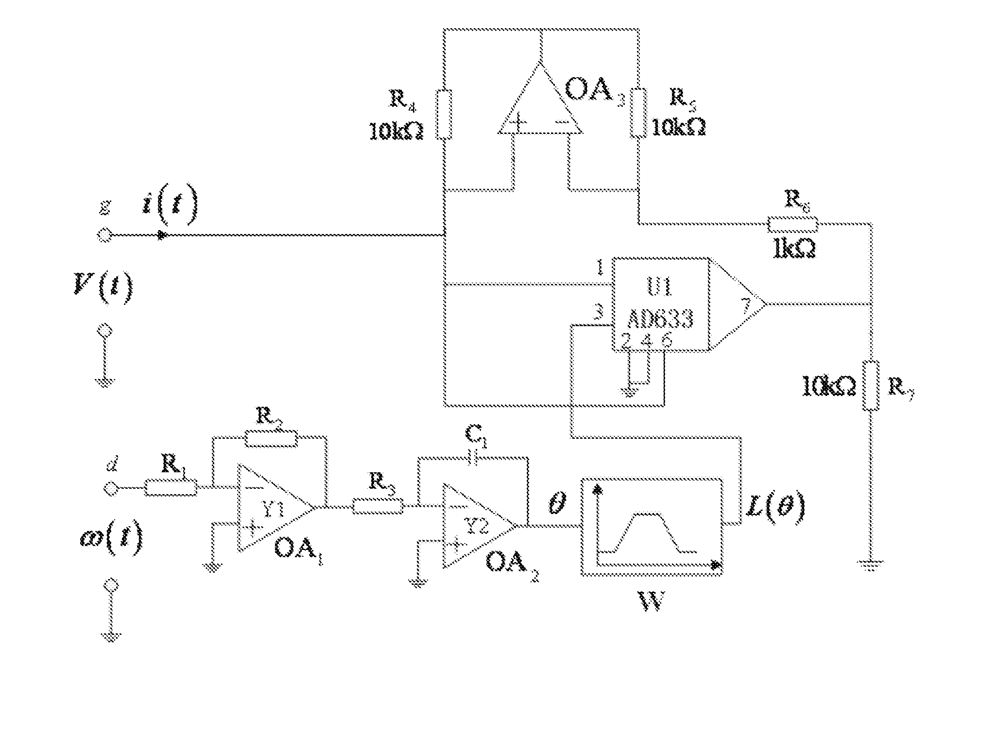
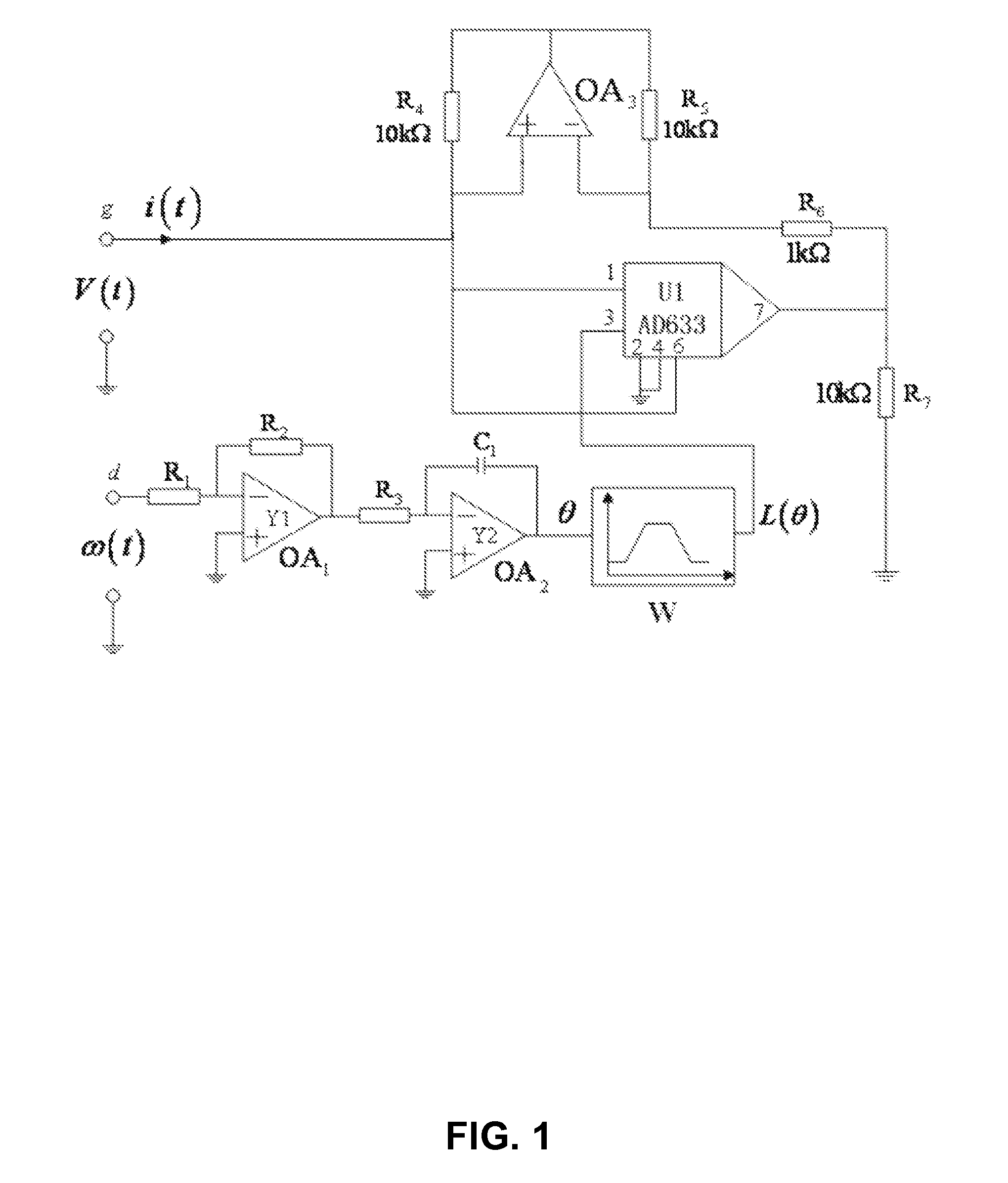
[0017]As shown in FIG. 1, the memristor-based linear modeling method for switched reluctance motors in the herein-described disclosure comprises:[0018]a) connecting the input of a non-inverting operational amplifier circuit with the input of an inverting operational amplifier circuit as the input terminal θ of a linear phase inductance characteristic element of a switched reluctance motor, adding the output of the non-inverting operational amplifier circuit with the output of the inverting operational amplifier circuit via a non-inverting additional operational circuit as the output terminal L(θ) of the linear phase inductance characteristic element of the switched reluctance motor, to construct a linear phase inductance characteristic element W for the switched reluctance motor;[0019]taking the positional angle θ of the rotor of the switched reluctance motor as the...


PUM


Abstract

A memristor linear modeling method for a switched reluctance motor. A non-inverting operational amplifier circuit and an inverting operational amplifier circuit are employed to construct a switched reluctance motor linear phase inductance characteristic element.

Description

CROSS-REFERENCE TO RELATED APPLICATIONS[0001]This application is a national phase entry under 35 U.S.C. §371 of International Patent Application PCT / CN2013 / 070929, filed Jan. 24, 2013, designating the United States of America and published as International Patent Publication WO 2014 / 063452 A1 on May 1, 2014, which claims the benefit under Article 8 of the Patent Cooperation Treaty to Chinese Patent Application Serial No. 201210403809.X 2012, filed Oct. 22, 2012.TECHNICAL FIELD[0002]This disclosure relates to electronic generally and more particularly to a memristor-based modeling method for switched reluctance motors, which is applicable to switched reluctance motors with any number of phases.BACKGROUND[0003]The modeling of a switched reluctance motor has direct influence on the optimal design, static and dynamic performance analysis, and evaluation of control strategy, etc., of the motor. It is difficult to apply the performance analysis and modeling methods for conventional motors...

Claims


Application Information

Patent Timeline
Patent Type & Authority Applications(United States)
IPC IPC(8): G06F17/11
CPCH02P23/14G06F17/11H02P25/08
Inventor CHEN, HAOLIANG, YANYU, DONGSHENG
Owner CHINA UNIV OF MINING & TECH
Learn More