Tiled image based scanning for head position for eye and gaze tracking

a technology of eye and gaze tracking and scanning for head position, which is applied in image enhancement, instruments, television systems, etc., can solve the problems of slowing down the initial read out of the full frame, affecting the accuracy of eye tracking, and requiring high sampling rates that cannot be provided using permanent full spatial resolution image acquisition

Active Publication Date: 2015-08-06
APPLE INC
View PDF6 Cites 50 Cited by
  • Summary
  • Abstract
  • Description
  • Claims
  • Application Information

AI Technical Summary

Benefits of technology

[0027]This enables a faster determination of the region of interest (ROI) for the actual eye or gaze tracking because initially only a part of the sensor area is read out, in contrast to reading out a full frame according to the prior art. Thus, the system does not need to operate with lower frame rates. Rather, the system can operate at a constant frame rate and pick-up speed is increased.
[0048]According to one embodiment, said searching the image data comprises using horizontal or vertical or combined horizontal and vertical binning, skipping, or sub-sampling of the image data of said initially read out part to accelerate search.

Problems solved by technology

Due to limited bandwidth of the camera bus, the frame rate of the system depends on size and spatial resolution of the grabbed image.
However, miscellaneous eye tracking applications require high sampling rates that cannot be provided using permanent full spatial resolution image acquisition.
However, this speed-up does not apply to the initial read out of the full frame.
However, various problems continue to exist.
Moreover, switching between full spatial resolution based image acquisition and ROI based image acquisition causes a delay in camera operation with many common camera models which results in a decreased data rate.
A final issue is that changes in data frame rate complicate the subsequent data analysis due to frame rate dependent parameters.

Method used


Image

  • Tiled image based scanning for head position for eye and gaze tracking
  • Tiled image based scanning for head position for eye and gaze tracking
  • Tiled image based scanning for head position for eye and gaze tracking

Examples


Embodiment Construction

[0069]In the following embodiments of the invention will be described in somewhat more detail. The embodiments for eye or gaze tracking described in the following can be used for just the purpose of determining and tracking the eye position or the gaze itself, or they may be applied in various fields such as marketing research, psychology, medical applications including surgery, control applications, simulators and generally as a part of human-machine-interfaces.

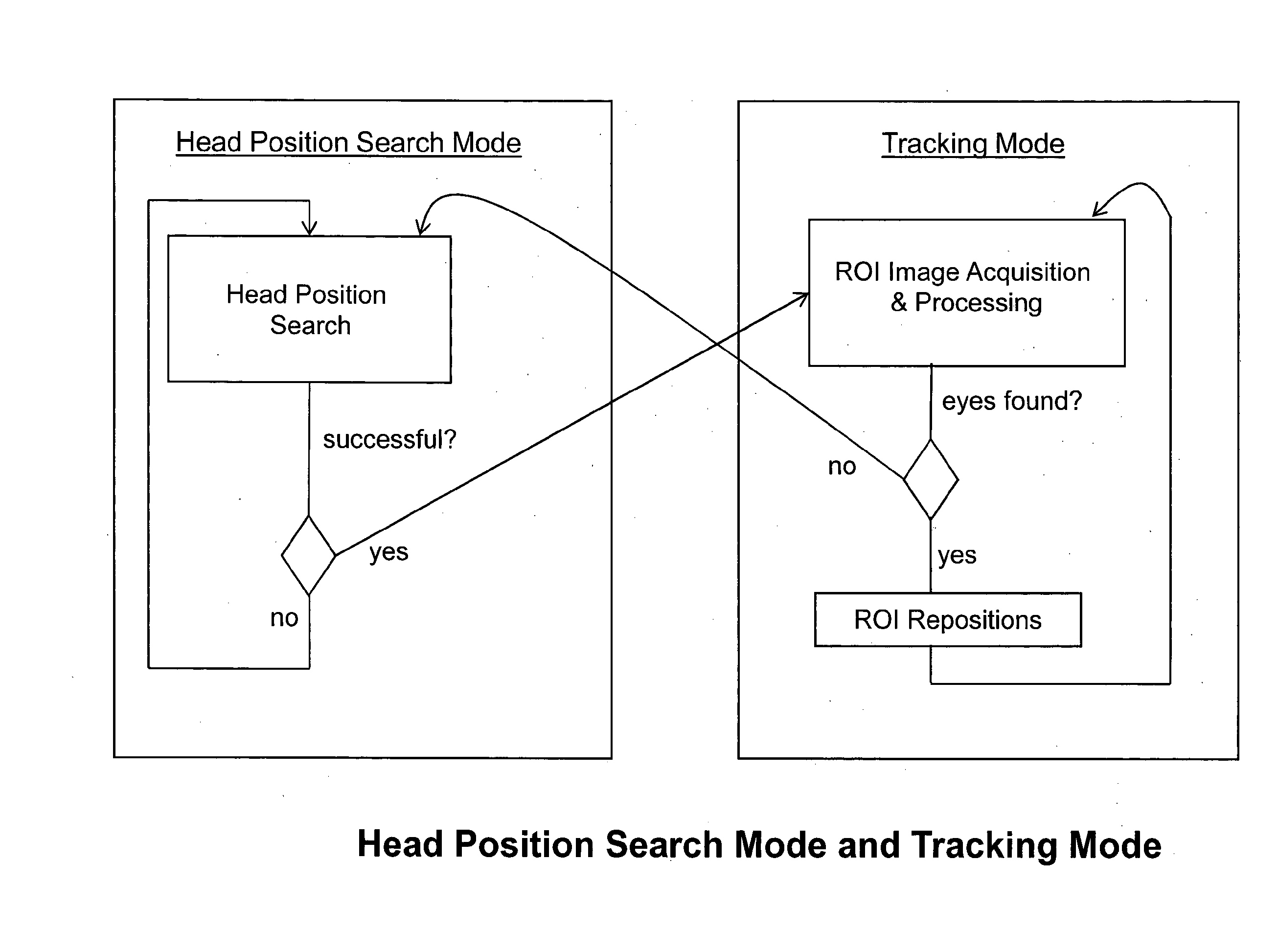
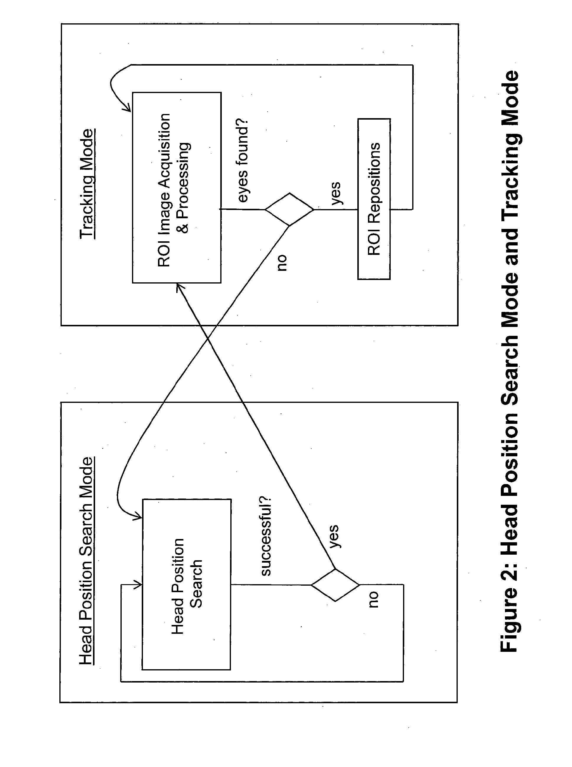
[0070]The system starts in Head Position Search Mode. The goal of this mode is to determine an initial ROI position that can be used in subsequent Tracking Mode. This transition can be realized as soon as there are enough features detected that allow the system to determine the head or eye position and derived from the head or eye position the initial position of the ROI for Tracking Mode.

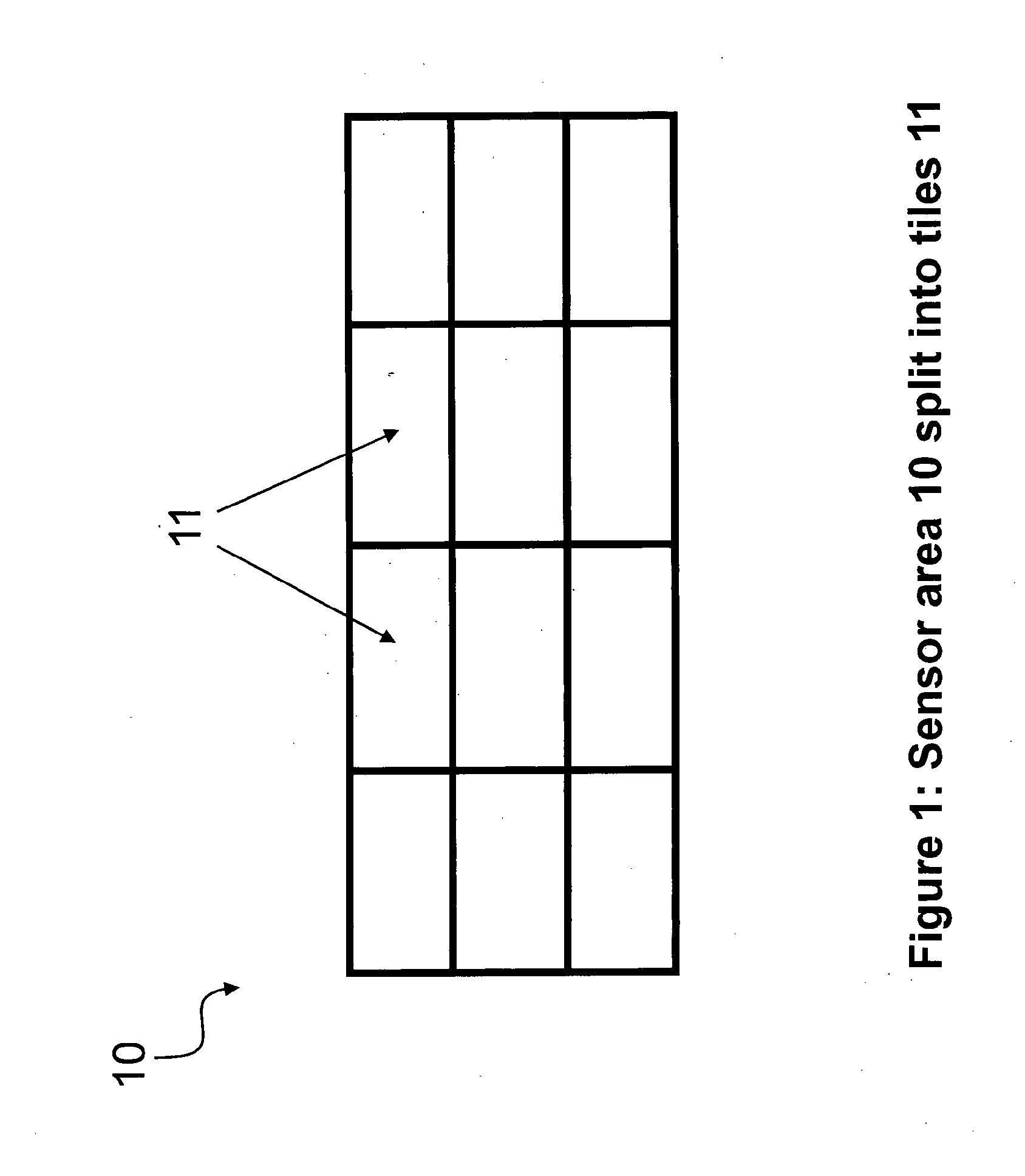
Scanning for Head Position using Tile Stitching

[0071]A system for eye or gaze tracking according to one embodiment starts in Head Position...


PUM


Abstract

An eye tracking method comprising: capturing image data by an image sensor; determining a region of interest as a subarea or disconnected subareas of said sensor which is to be read out from said sensor to perform an eye tracking based on the read out image data; wherein said determining said region of interest comprises: a) initially reading out only a part of the area of said sensor; b) searching the image data of said initially read out part for one or more features representing the eye position and / or the head position of a subject to be tracked; c) if said search for one or more features has been successful, determining the region of interest based on the location of the successfully searched one or more features, and d) if said search for one or more features has not been successful, reading out a further part of said sensor to perform a search for one or more features representing the eye position and / or the head position based on said further part.

Description

FIELD OF THE INVENTION[0001]This invention is concerned with eye gaze tracking, in particular with increasing the frame rate of camera based remote eye tracking systems using ROI based image acquisition and determining an initial ROI position for eye tracking.BACKGROUND OF THE INVENTION[0002]In current eye tracking systems camera images are processed to determine the position and / or gaze direction of an eye or the eyes. This can be done by detecting features in the image. Features are for example:[0003]Pupils[0004]Corneal Reflexes[0005]For each feature, typically size, contour and position are extracted. Subsequent processing calculates gaze vector and gaze point from these features.[0006]Camera based remote eye trackers provide a large working range for head movement. With a fixed focal length of the camera lens and without joints to change camera orientation, the working range has to be covered completely by the camera sensor.[0007]Due to limited bandwidth of the camera bus, the f...

Claims


Application Information

Patent Timeline
Patent Type & Authority Applications(United States)
IPC IPC(8): G06K9/00G06T7/00
CPCA61B3/113G06K9/00604G06T7/004G06K9/0061G06K9/00624G06K9/00362G06T7/70G06T7/73G06T7/246G06V40/19G06V40/193G06V40/10G06T11/60G06T2207/30201
Inventor RONNECKE, STEFANJABLONSKI, THOMASVILLWOCK, CHRISTIANNISTICO, WALTER
Owner APPLE INC
Why Eureka
Try Eureka