
Vibration-assisted apparatus for mixing immiscible liquids and for mixing powders with liquids or with other powders

Inactive Publication Date: 2015-08-13
BANUS CHRISTOPHER T
View PDF8 Cites 8 Cited by
  • Summary
  • Abstract
  • Description
  • Claims
  • Application Information

AI Technical Summary

Benefits of technology

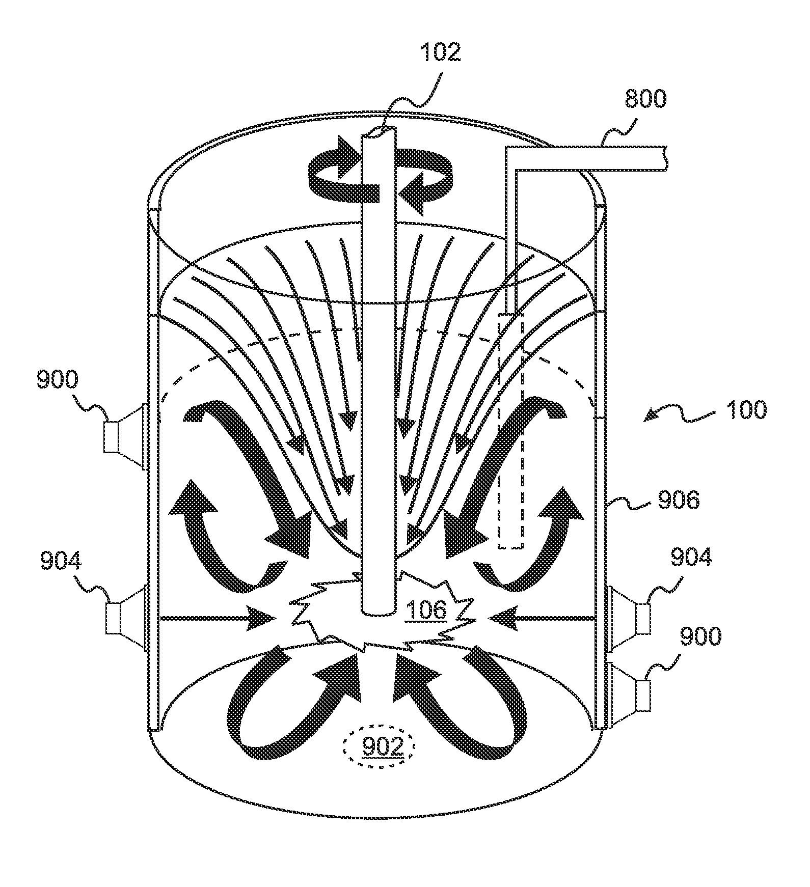
The patent is about a way to mix powders and liquids using vatable energy applicators on the container walls. The v Sobey and Dante Messina create a method that allows for faster and more effective mixing by using vibration and heating to break up clumps of powder particles and reduce viscosity. This method eliminates the need for shear forces or cooling and can even reduce the amount of liquid needed. It also helps to prevent boiling and escape of volatile liquid components.

Problems solved by technology

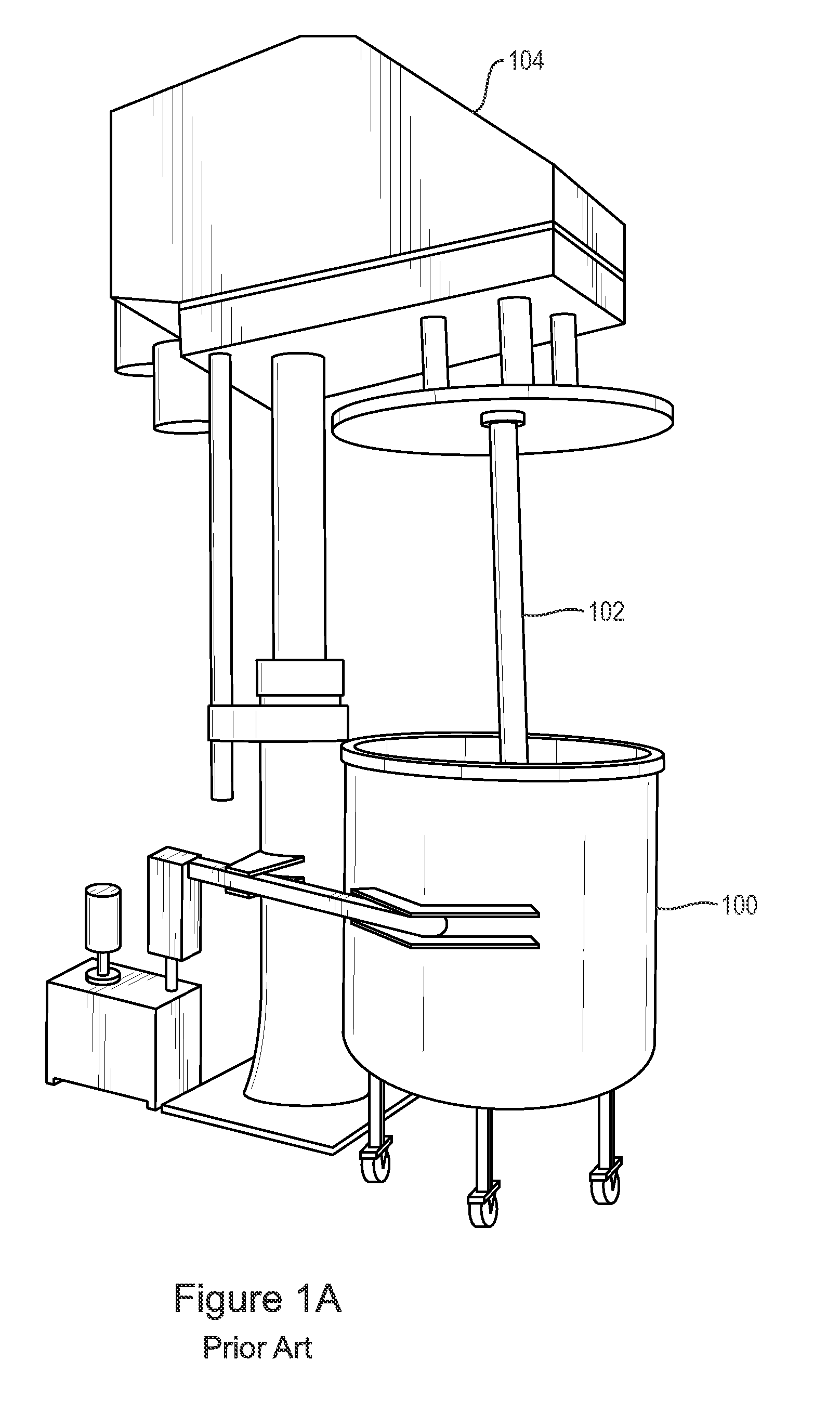
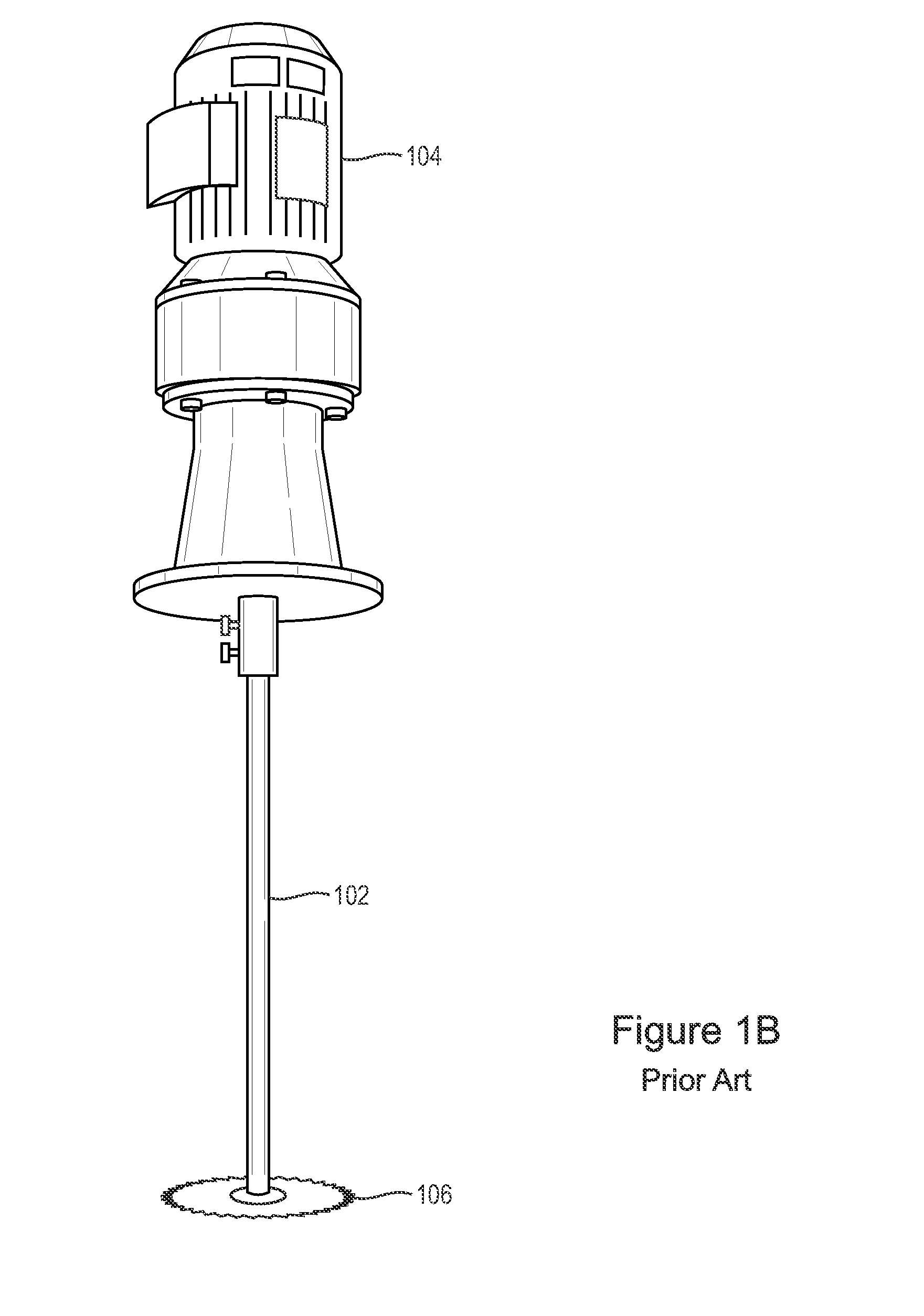
In general, vertical shaft batch mixers are not satisfactory for mixing two dry powders together, since dry powders lack the fluid viscosity necessary for establishing the convective flow illustrated in FIG. 1C, or even the local flow required for a vertical shaft planetary mixer.
The primary difficulty which must be overcome by a mixer in mixing immiscible liquids is to minimize the sizes of the droplets within the resulting emulsion.
However, depending on properties of the liquids such as their viscosities and surface tensions, once the droplets have been reduced to a certain size, further droplet size reduction becomes difficult as droplets of each liquid collide and coalesce with each other into larger droplets as they move through the mixture.
First, the granules of a powder do not naturally flow in the manner of a liquid.
Third, the granules of a powder can tend to adhere to the walls of a container and to the surfaces of an agitator, so that some fraction of the powder remains unmixed.
When immiscible liquid droplets and / or particle clumping are a concern, a batch mixer is generally used, since it is difficult for a continuous mixer to address the problem of droplet size and particle clumping.
However, this can lead to heating of the mixture, with a consequent loss of viscosity and / or damage to the mixture, so that active cooling of the mixing container 100 is sometimes needed to prevent damage to the mixture and to maintain sufficient viscosity for the sheer forces to be effective in breaking up the droplets and / or clumps.
For many of these industries, the energy consumed and the mixing time required are important contributors to the total cost of a production process.

Method used


Image

  • Vibration-assisted apparatus for mixing immiscible liquids and for mixing powders with liquids or with other powders
  • Vibration-assisted apparatus for mixing immiscible liquids and for mixing powders with liquids or with other powders
  • Vibration-assisted apparatus for mixing immiscible liquids and for mixing powders with liquids or with other powders

Examples


example 1

[0075]In this example a liquid, such as an adhesive or resin, or a liquid used in a paint or a food product, is combined with powder particles of a mineral or another material that must be evenly distributed into the liquid. The relative amount of the liquid can range from a large excess down to the minimum quantity needed to bind the particles together. It is generally more difficult to achieve complete mixing and dispersing of the particles for this situation of minimum liquid or binder. For the purposes of this example, the particle size distribution of the added solid material is assumed to be in the approximate range of 50-1000 microns, but can also be larger than 1000 microns or smaller than 50 microns.

[0076]In this example, the application of acoustic vibrational energy will cause the individual particles to move back and forth over a range from about 5% up to more than 100% of their diameters. By adjusting both the amplitude and the frequency of the vibrational energy, combi...

example 2

[0079]In this example, a mixture of a liquid adhesive or resin, or another liquid material is combined with a range of particles of a mineral or other material that must be evenly distributed and dispersed into the liquid. The relative amount of the liquid can range from a large excess down to the minimum quantity needed to bind the particles together. It is generally more difficult to achieve complete mixing and dispersing of the particles for this situation of minimum liquid or binder. For the purposes of this example, the particle size distribution of the added solid material is assumed to be in the approximate range of 0 to 100 microns, which are essentially powdered materials. For this range of particle sizes it will be very useful to apply ultrasonic vibration, ranging from low frequencies up to 15,000 Hz for large powder particles to much higher frequencies of 10,000 Hz to several MHz for very small particles, to cause the individual particles to move back and forth over a ra...

example 3

[0081]In this example, there is included a first quantity of a solid having the rather large particle size distribution of Example 1 and also a second quantity of a solid having the particle size distribution of Example 2. Therefore it will be seen that the application of both acoustic and ultrasonic vibration energies at the same time will facilitate the mixing of the entire range of included particle sizes.


PUM

PropertyMeasurementUnit
Lengthaaaaaaaaaa
Lengthaaaaaaaaaa
Lengthaaaaaaaaaa

Abstract

A batch or continuous mixer for mixing powders, immiscible liquids, or a powder with a liquid includes one or more vibrational energy applicators which propagate vibrational energy into the mixture, causing powders to flow like liquids and breaking up liquid droplets and powder clumps. In embodiments, the vibration frequency and amplitude are selected according to properties of the mixture components. Vibrations can be propagated through container walls, impellers, or other structures within the mixing container. Vibrated structures can be flexibly supported for enhanced propagation of the vibrations. Vibrational energy can be uniform throughout the container, or focused in a desired region. Ultrasonic energy can be simultaneously applied with acoustic energy.

Description

RELATED APPLICATIONS[0001]This application claims the benefit of U.S. Provisional Application No. 61 / 684,870, filed Aug. 20, 2012 and No. 61 / 710,021, filed Oct. 5, 2012, both of which are herein incorporated by reference in their entirety for all purposes.FIELD OF THE INVENTION[0002]The invention relates to mixing apparatus, and more particularly to apparatus for mixing immiscible liquids and / or mixing powders with liquids or with other powders.BACKGROUND OF THE INVENTION[0003]Mixing of immiscible liquids and / or mixing a particulate solid, herein referred to generically as a “powder,” with a liquid or with another powder are important requirements in many applications and industries. Examples of mixing two immiscible liquids are found throughout the chemical, petroleum, mining, and pharmaceutical industries. These include dispersing and emulsifying food components when preparing mayonnaise, or mixing latex with water to make water based paints.[0004]Powders are mixed with liquids du...

Claims


Application Information

Patent Timeline
IPC IPC(8): B01F11/02B01F3/12B01F3/08B01F27/96B01F29/60
CPCB01F11/0225B01F3/1242B01F3/0819B01F11/02B01F25/4333B01F27/0725B01F27/091B01F27/115B01F27/706B01F27/72B01F27/806B01F27/82B01F27/85B01F27/95B01F27/96B01F29/40118B01F29/60B01F31/83B01F31/84B01F31/86B01F31/85B01F27/90B01F35/422B01F23/551B01F23/4111B01F31/80
Inventor BANUS, CHRISTOPHER T.
Owner BANUS CHRISTOPHER T
Learn More