Motorized window treatment

a motorized and window treatment technology, applied in the direction of door/window protective devices, high-level techniques, shutters/movable grilles, etc., can solve the problems of requiring subsequent repair, high cost of running additional ac main line voltage wiring to the electronic drive unit, and unsatisfactory aesthetics, so as to increase and lower the covering material, not to achieve the effect of longer (and more practical) li

Active Publication Date: 2015-08-13
LUTRON TECH CO LLC
View PDF3 Cites 61 Cited by
  • Summary
  • Abstract
  • Description
  • Claims
  • Application Information

AI Technical Summary

Benefits of technology

[0009]As described herein, a low-cost, quiet, battery-powered motorized window treatment is configured to control the position of a covering material (e.g., a cellular shade fabric or a roller shade fabric) that is adapted to hang in front of an opening, such as a window. The motorized window treatment may comprise a motor drive unit having a motor for driving a drive assembly to raise and lower the covering material. The motorized window treatment may comprise one or more battery packs configured to receive batteries for powering the motor drive unit of the motorized window treatment. The batteries may not be expensive to replace and may have a much longer (and more practical) lifetime than the typical prior art battery-powered motorized window treatment (e.g., approximately three years). The batteries may be located out of view of a user of the motorized window treatment (e.g., in a headrail or in a battery compartment). The motorized window treatment may be adjusted to a service position to provide access to the batteries to allow for easy replacement of the batteries without unmounting any portion of the motorized window treatment. In addition, the motorized window treatment may make battery power more convenient for the user by controlling the motor at a reduced speed when the battery voltage is low (e.g., to harvest the remaining battery power and to signal to the user that the batteries need to be replaced) and by preventing movement of the covering material when the battery voltage is too low (e.g., to reserve enough energy to move the covering material to the fully-raised position one last time).
[0011]Since the motorized window treatment is battery-powered and is configured to be controlled in response to wireless input signals transmitted by an input device, the motorized window treatment may be installed without requiring any additional wiring. The motorized window treatment may be easily programmed to operate in response to the wireless signals transmitted by the input device. In addition, the upper and lower limits of the motorized window treatment may be easily programmed using the input device. The battery-powered motorized window treatment may also be integrated as part of a larger load control system, such as, an RF load control system, and may be configured to transmit digital messages including, for example, data regarding the battery voltage of the batteries, or the temperatures measured by the temperature sensors.
[0012]The motorized window treatment may use various power-saving methods to lengthen the lifetime of the batteries. For example, the motorized window treatment may comprise a constant-force spring operatively coupled to a drive shaft and a motor of the motorized window treatment for reducing the amount of power consumed as the covering material is raised and lowered. If the motorized window treatment includes an RF receiver for receiving RF signals, the motorized window treatment may be configured to use an RF sub-sampling technique to put the RF receiver to sleep for longer periods of time than typical prior art RF receivers to thus conserve battery power. When the battery voltage is low (i.e., near the end of the lifetime of the batteries), the motorized window treatment may be configured to reduce the speed at which the motor rotates to conserve additional battery power and thus extend the lifetime of the batteries.
[0016]Further, a motorized window treatment may comprise a motor drive unit including a rotational position sensor to enable the motor drive unit to sense movement of an output shaft of a motor. The controller may be configured to determine the position of a bottom end of a covering material in response to the rotational position sensor. The motor drive unit may also comprise a memory coupled to the controller to store position data related to the determined position. The motorized window treatment may also comprise at least one battery pack configured to hold at least one battery for producing a battery voltage to power the motor drive unit, and a supplemental power source for the controller. The supplemental power source may be configured to maintain a charged voltage for a period of time adequate to maintain the position date when the at least one battery is removed from the battery pack. The at least one battery may be removed from the battery pack without loss of the position data.

Problems solved by technology

Unfortunately, this requires that electrical wires to be run from the power source to the electronic drive unit.
Running additional AC main line voltage wiring to the electronic drive unit can be very expensive, due to the cost of the additional electrical wiring as well as the cost of installation.
In addition, if the pre-existing wiring runs behind a fixed ceiling or wall (e.g., one comprising plaster or expensive hardwood), the electrician may need to breach the ceiling or wall to install the new electrical wiring, which will thus require subsequent repair.
However, this sort of installation requires the permanent use of one of the outlets of the electrical receptacle and is aesthetically unpleasing due to the external electrical wires.
However, the typical prior art battery-powered motorized window treatments have suffered from poor battery life (such as, one year or less), and have required batteries that are difficult and expensive to replace.
The batteries may not be expensive to replace and may have a much longer (and more practical) lifetime than the typical prior art battery-powered motorized window treatment (e.g., approximately three years).

Method used


Image

  • Motorized window treatment
  • Motorized window treatment
  • Motorized window treatment

Examples


Embodiment Construction

[0044]The foregoing summary, as well as the following detailed description of the preferred embodiments, is better understood when read in conjunction with the appended drawings. For the purposes of illustrating the invention, there is shown in the drawings an embodiment that is presently preferred, in which like numerals represent similar parts throughout the several views of the drawings, it being understood, however, that the invention is not limited to the specific methods and instrumentalities disclosed.

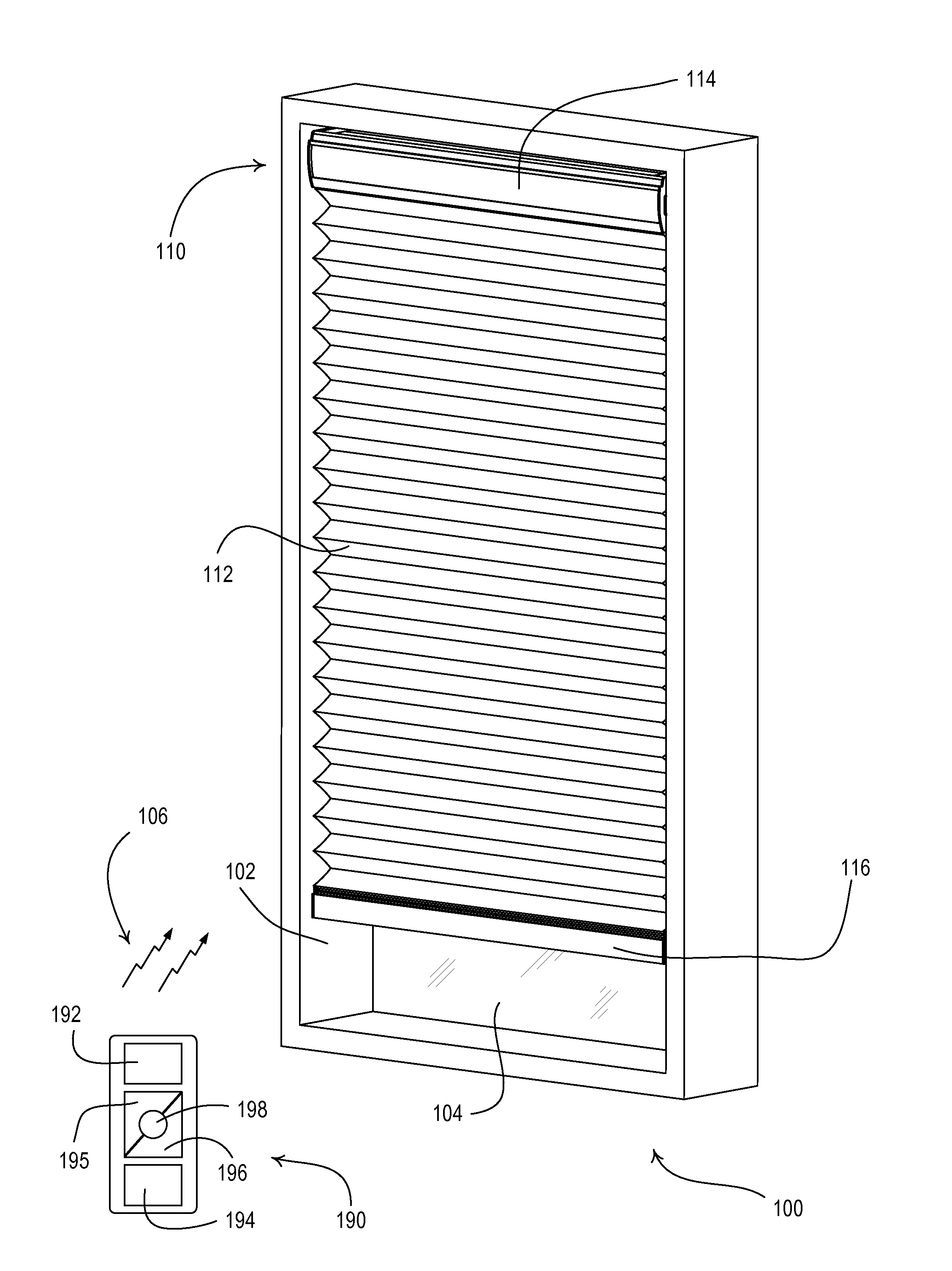
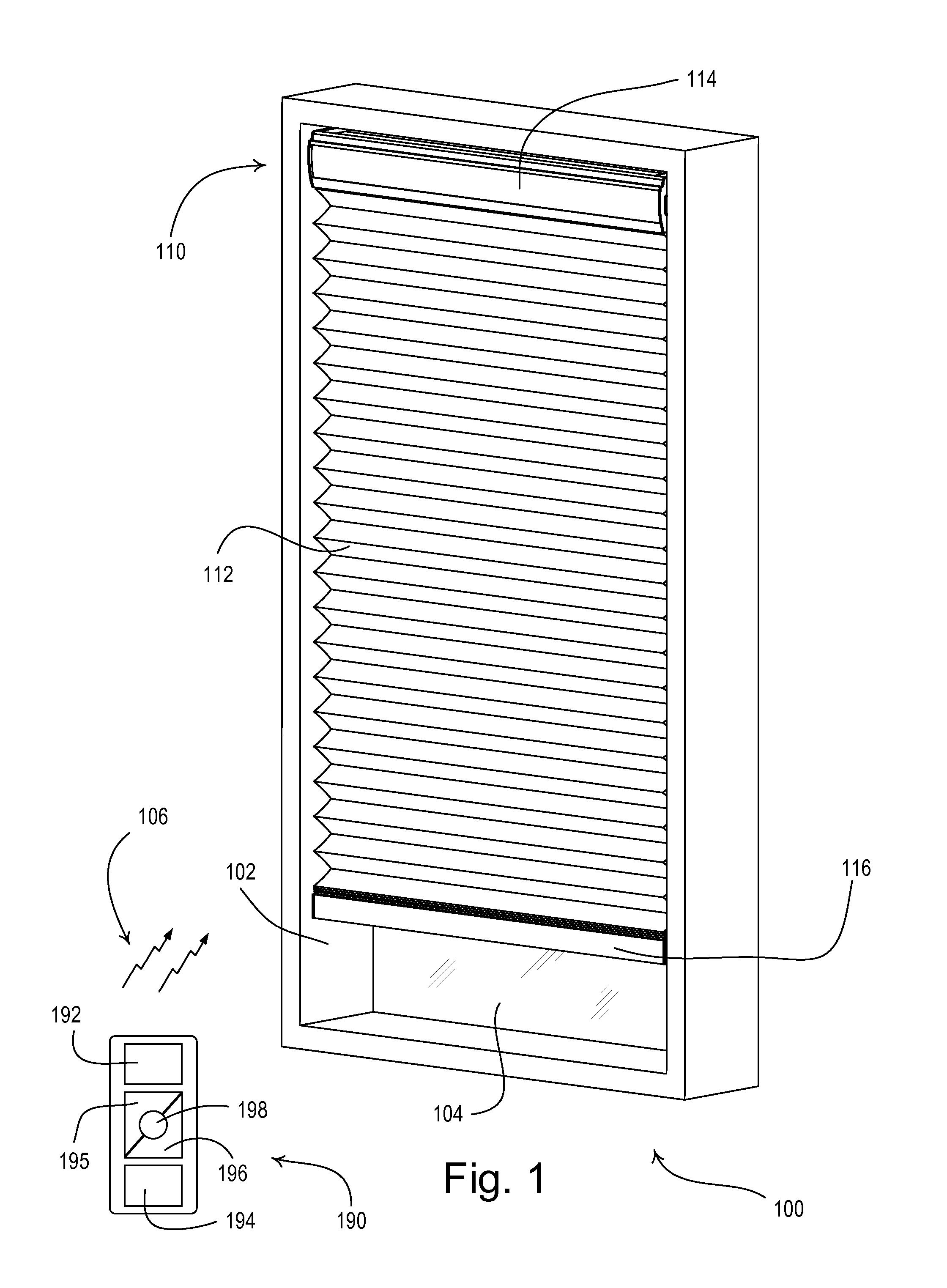
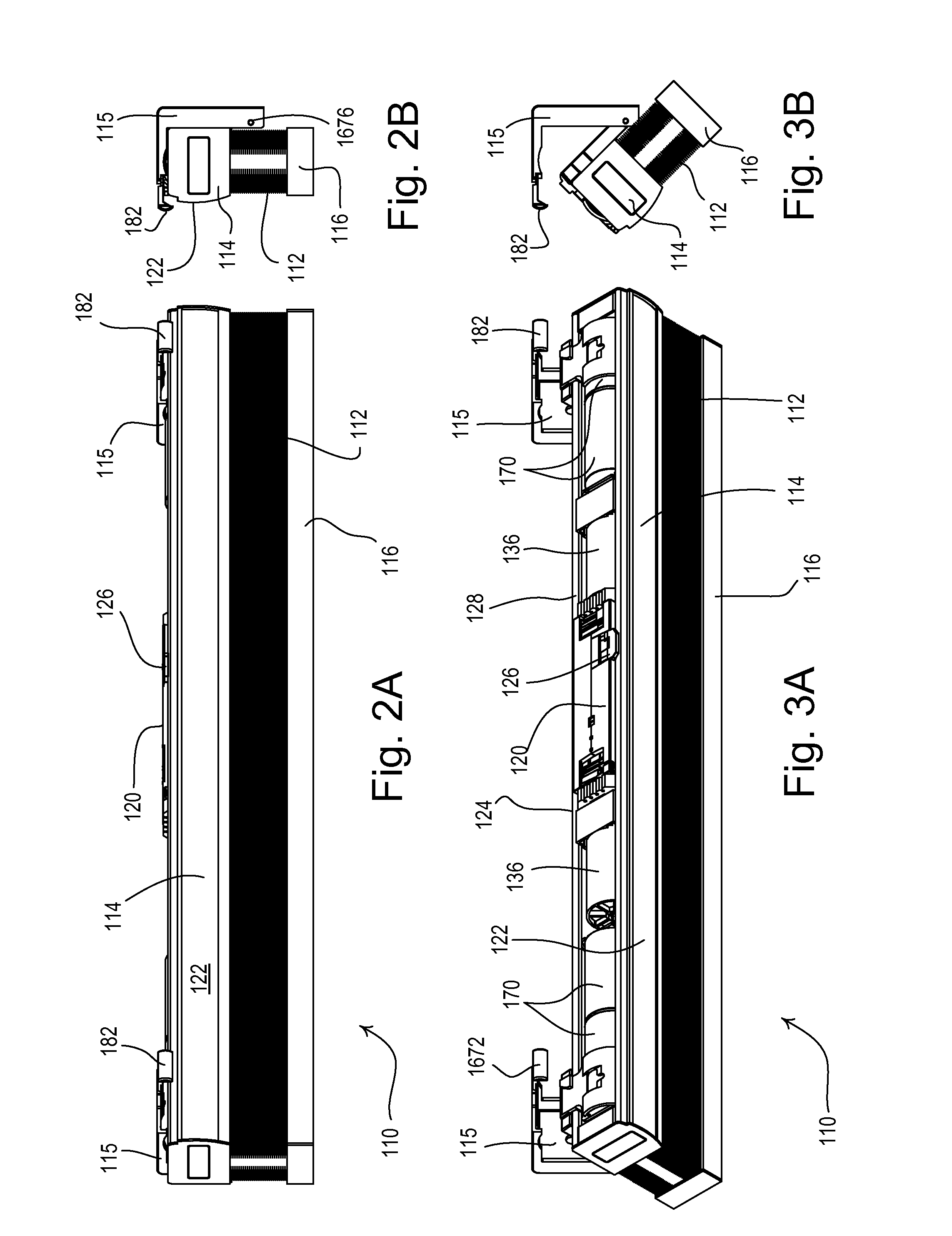
[0045]FIG. 1 is a perspective view of a motorized window treatment system 100 having a battery-powered motorized window treatment 110 mounted in an opening 102, for example, in front of a window 104. The battery-powered motorized window treatment 110 may comprise a covering material, for example, a cellular shade fabric 112 as shown in FIG. 1. The cellular shade fabric 112 may have a top end connected to a headrail 114 and a bottom end connected to a weighting element 116. The h...


PUM


Abstract

A motorized window treatment may provide a low-cost solution for controlling the amount of daylight entering a space through a window. The window treatment may include a covering material (e.g., a cellular shade fabric or a roller shade fabric), a drive assembly for raising and lowering the covering material, and a motor drive unit including a motor configured to drive the drive assembly to raise and lower the covering material. The motorized window treatment may comprise one or more battery packs configured to receive batteries for powering the motor drive unit. The batteries may be located out of view of a user of the motorized window treatment (e.g., in a headrail or in a battery compartment). The motorized window treatment may use various power-saving methods to lengthen the lifetime of the batteries, e.g., to reduce the motor speed to conserve additional battery power and extend the lifetime of the batteries.

Description

CROSS REFERENCES TO RELATED APPLICATIONS[0001]This application is a continuation-in-part of U.S. patent application Ser. No. 14 / 579,024, filed Dec. 22, 2014, which is a divisional application of U.S. patent application Ser. No. 13 / 415,084, filed Mar. 8, 2012, now U.S. Pat. No. 8,950,461, issued Feb. 10, 2015, which is a non-provisional application of commonly-assigned U.S. Provisional Application No. 61 / 451,960, filed Mar. 11, 2011; U.S. Provisional Application No. 61 / 530,799, filed Sep. 2, 2011; and U.S. Provisional Application No. 61 / 547,319, filed Oct. 11, 2011, all entitled MOTORIZED WINDOW TREATMENT, the entire disclosures of which are hereby incorporated by reference.BACKGROUND[0002]1. Field of the Invention[0003]The present invention relates to a motorized window treatment, and more specifically, to a low-cost, quiet, battery-powered motorized window treatment that is characterized by an ultra-low power consumption that makes battery power more convenient for a user and resul...

Claims


Application Information

Patent Timeline
Patent Type & Authority Applications(United States)
IPC IPC(8): E06B9/72
CPCE06B2009/6809E06B9/72E06B9/32E06B9/322E06B9/62H04W52/0238H04W52/0245H04W52/0287E06B2009/2625E06B2009/6818E06B2009/6872H04W52/0277E06B9/323E06B9/42Y02D30/70
Inventor ADAMS, JASON O.BLAIR, EDWARD J.COONEY, ANDREW KARLJAIN, SOUMYAKIRBY, DAVID A.LUNDY, STEPHENMIERTA, JUSTIN J.MISTARZ, DANIEL W.NEWMAN, JR., ROBERT C.OGDEN, JR., PETER W.ROE, JONATHAN L.WU, CHEN MINGZERNHELT, JUSTIN M.CHAMBERS, SAMUEL F.
Owner LUTRON TECH CO LLC
Why Eureka
Try Eureka