Patient Communication in Magnetic Resonance Tomography

a technology patient communication, applied in the field of magnetic resonance tomography, can solve the problems of inability to use permanent magnet sound transducers, patients' and/or operators' perception of disruptive types of compressed air hoses, and achieve the effect of small surface area and low induction

Inactive Publication Date: 2015-08-13
SIEMENS AG
View PDF4 Cites 7 Cited by
  • Summary
  • Abstract
  • Description
  • Claims
  • Application Information

AI Technical Summary

Benefits of technology

[0017]The actuator may be a piezoelectric actuator. Magnetic components may thus be avoided. In addition, piezoelectric actuators may have relatively small surfaces, such that a low induction of eddy currents in the magnetic resonance tomograph is to be expected. In this case the actuator may be formed from at least one piezoelectric layer disposed on at least one side on a membrane or a housing section of the component. The membrane or the housing section is bendable by a changing shape of the piezoelectric layer. This allows flexural vibrations of the membrane or of the housing section to be created. The excitation of the flexural vibration may be performed in such cases in accordance with the monomorphic or bimorphic principle, in which the piezoelectric layer contracts or expands depending on the control signal, while the expansion of the membrane or of the housing section remains essentially the same. This leads to the bending of the membrane or of the housing section. In order to amplify this effect a piezoelectric layer may be disposed on both sides of the membrane or of the housing section. The two piezoelectric layers are operated with different polarities, such that a control signal that leads to the expansion of one of these layers, leads to contraction of the other layer. Thus the two piezoelectric layers act together in order to create a bending. The use of a piezoelectric layer for bending a membrane or a housing section provides a flat actuator with a large stroke.

Problems solved by technology

Transmission of acoustic information to a patient and from a patient is relatively complex however.
On the other hand, high magnetic fields may be attained in magnetic resonance tomography, which is why the use of sound transducers with permanent magnets is not possible.
However, these types of compressed-air hoses are frequently perceived as disruptive by patients and / or by operators.

Method used


Image

  • Patient Communication in Magnetic Resonance Tomography
  • Patient Communication in Magnetic Resonance Tomography
  • Patient Communication in Magnetic Resonance Tomography

Examples


Embodiment Construction

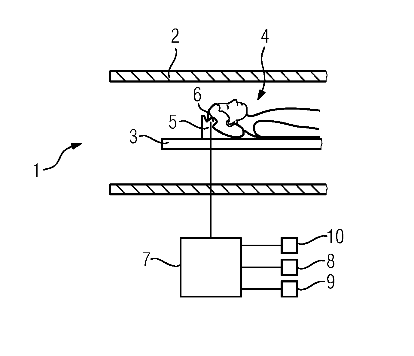
[0024]FIG. 1 shows a sectional, partial view of a magnetic resonance tomograph 1. A patient 4 is introduced on a couch 3 into a bore 2 of the magnetic resonance tomograph 1. In this case the head of the patient 4 is supported by a component 5 configured as a head support. A contact area 6 is provided on the component 5, on which the temple of the patient 4 rests during the imaging with the magnetic resonance tomograph 1.

[0025]Disposed in the contact area 6 is an actuator not shown in FIG. 1. Upon activation by a control signal, the actuator moves the surface of the contact area 6 facing toward the patient 4. The control signal is provided by the control device 7. The control signal involves an audio signal, such as speech. The patient communication device of the magnetic resonance tomograph 1, in addition to the actuator not shown in the figure and the control device 7, additionally includes a microphone 8 and a loudspeaker 9, which are both disposed outside the bore 2 of the magnet...


PUM


Abstract

A magnetic resonance tomograph has a component on which the head of a patient rests during imaging in a contact area. The magnetic resonance tomograph also has a patient communication device for communicating information to the patient. The patient communication device has a control device and also an actuator assigned to the contact area. The actuator, upon actuation with electric control signals by the control device, vibrates the surface of the contact area.

Description

[0001]This application claims the benefit of DE 102014202301.7, filed on Feb. 7, 2014, which is hereby incorporated by reference in its entirety.FIELD[0002]The invention relates to magnetic resonance tomography.BACKGROUND[0003]When patients are being examined in a magnetic resonance tomograph, an exchange of information with the patient is frequently required. Patients are given instructions about holding their breath or the like. On the other hand, communication between the patient and other people may soothe anxieties and uncertainties, especially when a magnetic resonance tomograph with a relatively narrow bore is used. Transmission of acoustic information to a patient and from a patient is relatively complex however. On the one hand, hearing protection for patients, which attenuates acoustic signals, is frequently used during magnetic resonance tomography examinations. On the other hand, high magnetic fields may be attained in magnetic resonance tomography, which is why the use ...

Claims


Application Information

Patent Timeline
Patent Type & Authority Applications(United States)
IPC IPC(8): G01R33/28G01R33/341A61B5/00A61B5/055
CPCG01R33/283A61B5/0555A61B5/7455A61B5/0042G01R33/341A61B5/055A61B5/6814
Inventor MATSCHL, VOLKER
Owner SIEMENS AG
Why Eureka
Try Eureka