Sewing machine

a sewing machine and sewing technology, applied in the field of sewing machines, can solve the problems of cumbersome and troublesome generation of boring data, and achieve the effect of easy formation of cut patterns

Active Publication Date: 2015-08-20
BROTHER KOGYO KK
View PDF5 Cites 4 Cited by
  • Summary
  • Abstract
  • Description
  • Claims
  • Application Information

AI Technical Summary

Benefits of technology

[0008]Therefore, an object of the disclosure is to provide a sewing machine which can easily form a cut pattern desired by the user on the workpiece cloth.

Problems solved by technology

The generation of boring data takes a lot of trouble and is cumbersome.

Method used


Image

  • Sewing machine
  • Sewing machine
  • Sewing machine

Examples


fourth embodiment

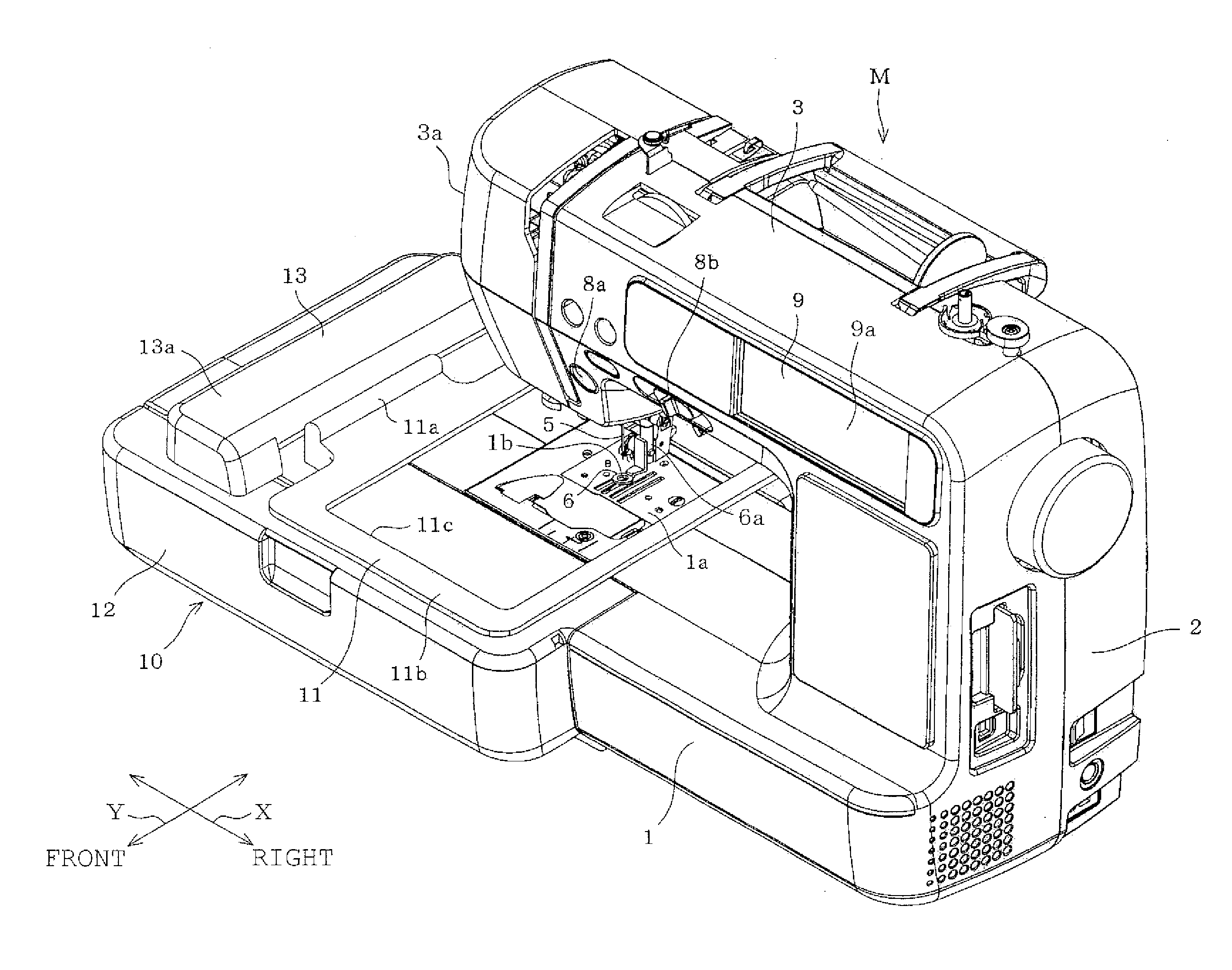
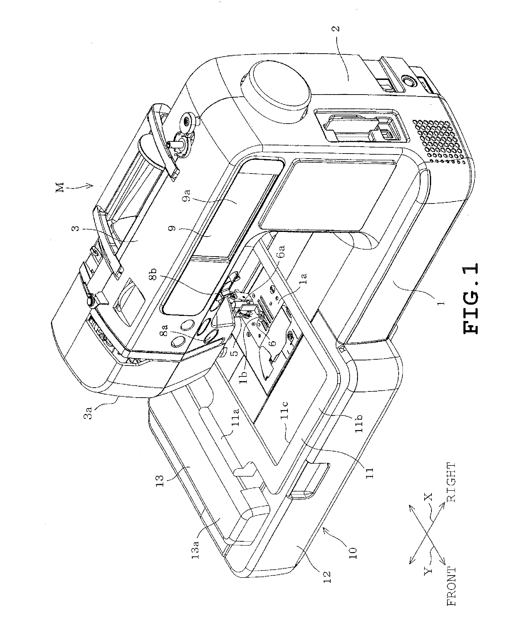
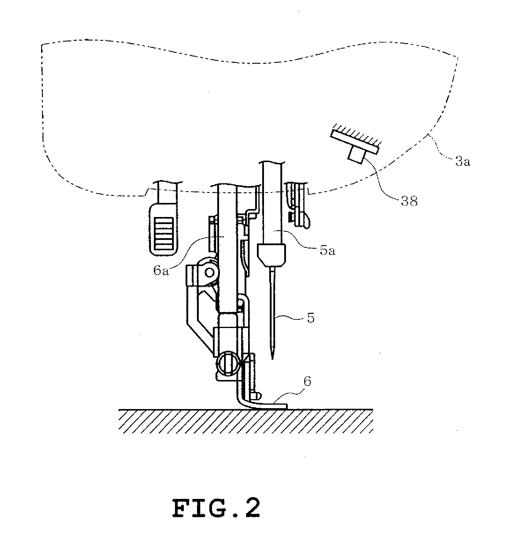
[0079]In the free motion cutting, the control device 39 specifies a moving direction of the workpiece cloth in the case where the user moves the workpiece cloth in any direction, and the control device 39 controls a rotating mechanism 87 so that the direction of the blade 60a is changed according to the specified moving direction. The up-down drive mechanism 86 is driven to vertically reciprocate the cutting needle 60, thereby forming a cut in the workpiece cloth according to a moving direction of the workpiece cloth by the blade 60a of the cutting needle 60. The moving direction of the workpiece cloth is specified based on an image of the workpiece cloth taken by the camera 38 or detection signals generated by the encoders 25 and 33 in the case where the moving table 11 is moved with the workpiece cloth being placed on the moving table 11. In the following description of the working, the moving direction is to be specified based on an image of workpiece cloth taken by the camera 38...

second embodiment

[0099]As described above, the sewing machine M of the second embodiment includes the first pitch setting unit which sets to the first pitch length the interval of cuts formed on the workpiece cloth CL by the up-down movement of the cutting needle 60, that is, the pitch length. The control unit controls the up-down drive mechanism 86 based on the detection results of the detection unit, so that cuts having the first pitch length set by the first pitch setting unit are formed on the workpiece cloth CL. The control unit further controls the rotational drive mechanism 87 so that the orientation of the blade 60a is changed according to the moving direction of the workpiece cloth CL.

[0100]According to the above-described configuration, when the user moves the workpiece cloth CL placed on the bed in any direction, the detection unit can detect a movement amount and a moving direction of the workpiece cloth CL. Consequently, the cutting needle 60 is rotated based on the results of detection...

third embodiment

[0103]Further, in the third embodiment, a number setting screen (not shown) is displayed on the display 9 in starting the free motion cut. The number setting screen is provided for setting the number of reciprocation of the cutting needle 60 to a predetermined number of times. More specifically, the user sets the number of reciprocation of the cutting needle 60 by the touch operation onto the touch panel 9a in order to optionally set a cut position of the second pitch length (discontinuities of cuts in the cut pattern). In this case, a setting screen (not shown) to set the second pitch length may be displayed on the display 9, so that the second pitch length may be set to any value by the touch operation on the touch panel 9a. The control device 39, the touch panel 9a, the display 9 and the like constitute a second pitch setting unit which sets the pitch length to the second pitch length and a number setting unit which sets the number of reciprocation of the cutting needle 60 to the...


PUM


Abstract

A sewing machine includes a detection unit configured to detect a moving direction of an object to be processed when the object placed on a sewing machine bed is moved in any direction, a cutting needle having a distal end formed with a blade edge and configured to form a cut in the object, an up-down drive mechanism configured to reciprocate the cutting needle in an up-down direction, a rotational drive mechanism configured to rotate the cutting needle about a rotation axis line of the cutting needle, and a control device configured to control the up-down drive mechanism and the rotational drive mechanism based on a result of detection by the detection unit so that the cutting needle forms the cut in the object while changing an orientation of the blade edge according to the moving direction of the object.

Description

CROSS-REFERENCE TO RELATED APPLICATIONS[0001]This application is based upon and claims the benefit of priority from the prior Japanese Patent Application No. 2014-029595 filed on Feb. 19, 2014, the entire contents of which are incorporated herein by reference.BACKGROUND[0002]1. Technical Field[0003]The present disclosure relates to a sewing machine.[0004]2. Related Art[0005]A sewing machine has conventionally been known which sews an embroidery pattern based on embroidery data. This type of sewing machine includes a storage device storing embroidery data of a plurality of embroidery patterns. A user selects a desirable one of the embroidery patterns. The sewing machine reads the embroidery data of the selected embroidery pattern and instructs a transfer mechanism to transfer an embroidery pattern holding a workpiece cloth while a needle bar with a needle attached thereto is being moved up and down by an up-down moving mechanism. The embroidery pattern is sewn on the workpiece cloth ...

Claims


Application Information

Patent Timeline
Patent Type & Authority Applications(United States)
IPC IPC(8): D05B19/12D05B81/00
CPCD05B37/063D05C7/04D05B19/12D05B81/00D05D2207/04
Inventor OTA, MANAMISHIMIZU, AKIENISHIMURA, YOSHIONAKAMURA, YOSHINORINOMURA, YUTAKAABE, DAISUKEIHIRA, YUKI
Owner BROTHER KOGYO KK
Why Eureka
Try Eureka