Magnetic field detecting device

Active Publication Date: 2015-08-20
AICHI STEEL
View PDF4 Cites 7 Cited by
  • Summary
  • Abstract
  • Description
  • Claims
  • Application Information

AI Technical Summary

Benefits of technology

[0035]Therefore, an information amount (signal voltage), which is almost twice more than that of the magnetic impedance sensor according to the conventional art, can be obtained. Thus, the ratio of the output of the magnetic impedance element relative to the noise of the electronic circuit of the signal processing device is improved and a more sensitive magnetic field detecting device is realized.
[0036]On the magnetic field detecting device of the fifth aspect of the present invention having the construction described above, according to the first aspect of the present invention, even in a case where the magnetic field included in the two alternate current damped oscillation voltages output at the rise time and the fall time of the pulse current is applied, the hysteresis component cancel means provided in the signal processing device cancels the generated hysteresis components. Thus, the offset error can be eliminated, so that the stability of zero point is improved and an effect of realizing a magnetic field detecting device having higher accuracy is attained. So, this offset error of the hysteresis component can be eliminated. This improves the stability of zero point and attains the effect of realizing a magnetic field detecting device having higher accuracy.
[0037]On the magnetic field detecting device of the sixth aspect of the present invention having the construction described above, according to the fourth aspect of the present invention, the differential operating device comprising the signal processing device, respectively sample-holds the alternate current damped oscillation voltages at the rise time and the fall time of the pulse current output of the magnetic impedance element, operates the difference between the two sample-held voltages, by obtaining substantively a sum of the two alternate current damped oscillation voltages output at the rise time and the fall time of the pulse current, and improves the ratio of the output of the magnetic imped

Problems solved by technology

However, in comparison to a case of signal processing based on both the Alternate current damped oscillation voltages Vr and −Vf at the rise and fall times of the pulse current, processed information (signal voltage) is lost by al

Method used


Image

  • Magnetic field detecting device
  • Magnetic field detecting device
  • Magnetic field detecting device

Examples


first embodiment

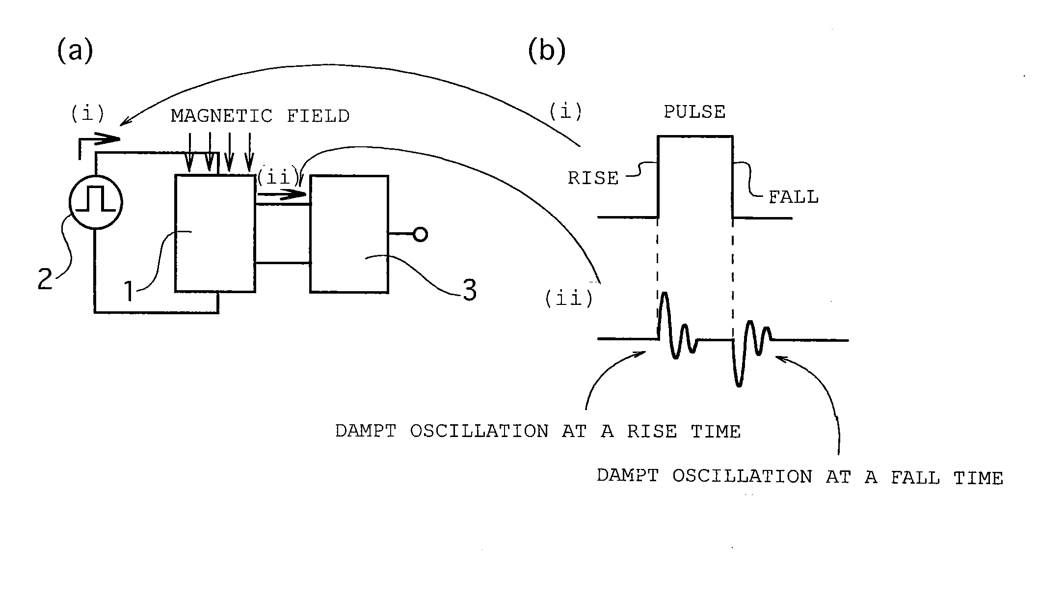
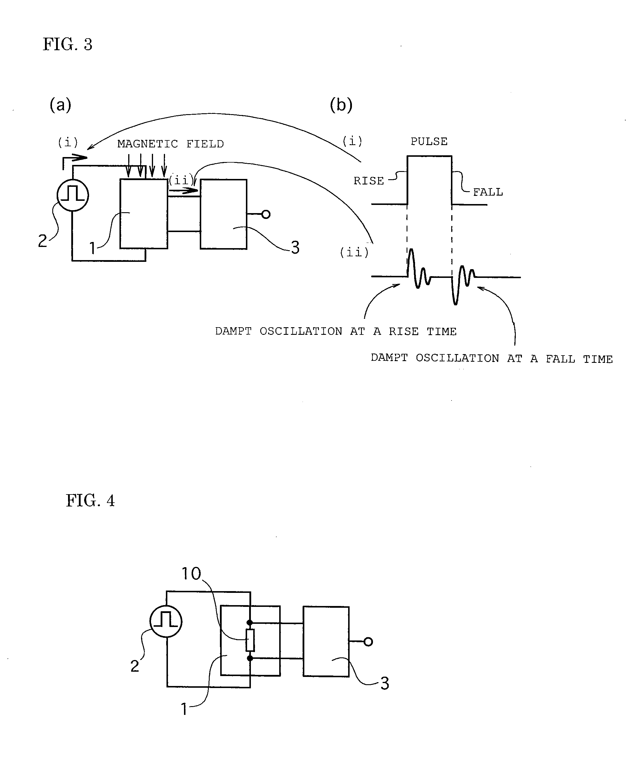
[0055]A magnetic field detecting device of a first embodiment is constructed in such a manner that as shown in FIG. 3(a), a pulse current is applied to an amorphous wire of a magnetic impedance element 1 by a pulse oscillation circuit 2, and based on two alternate current (AC) damped oscillation voltages output at a rise time and a fall time of the pulse current from the magnetic impedance element, a signal processing device 3 outputs as an external magnetic field signal around the amorphous wire.

[0056]In addition, “outputting the output signal in response to the external magnetic field around the amorphous wire based on the alternate current damped oscillation voltages or waveforms of the voltages” indicates that signal processing is performed depending on peak values, instantaneous values, average values, effective values of the two alternate current damped oscillation voltages output at the rise time and the fall time of the pulse current from the magnetic impedance element, or a...

second embodiment

[0058]A magnetic field detecting device of a second embodiment is constructed in such a manner that as shown in FIG. 4, since the pulse current is applied to the magnetic impedance element 1 by the pulse oscillation circuit 2, the alternate current damped oscillation voltages at the rise time and the fall time of the pulse current are output between two electrodes of an amorphous wire 10 constituting the magnetic impedance element 1, and the signal processing device 3 processes signals of the output alternate current damped oscillation voltages and outputs as the external magnetic field signal around the amorphous wire.

[0059]In the magnetic field detecting device of the second embodiment, based on the two alternate current damped oscillation voltages output at the rise time and the fall time of the pulse current from the part between the two electrodes of the amorphous wire 10 constituting the magnetic impedance element 1, the signal processing device 3 outputs as the external magne...

third embodiment

[0060]A magnetic field detecting device of a third embodiment is constructed in such a manner that as shown in FIG. 5, the alternate current damped oscillation voltages at the rise time and the fall time of the pulse current are output between two electrodes of a detecting coil 11 wound around the amorphous wire 10 constituting the magnetic impedance element 1, and based on the two alternate current damped oscillation voltages output at the rise time and the fall time of the pulse current from the detecting coil, the signal processing device 3 outputs as a magnetic field signal around the amorphous wire 10.

[0061]In the magnetic field detecting device of the third embodiment, based on the two alternate current damped oscillation voltages output at the rise time and the fall time of the pulse current between the two electrodes of the detecting coil 11 which is wound around the amorphous wire 10, the signal processing device 3 outputs as the magnetic field signal around the amorphous w...


PUM


Abstract

A magnetic field detecting device which comprises a magnetic impedance sensor including a magnetic impedance element 1 in which a detecting coil 11 wound around an amorphous wire 10 for detecting and outputting the external magnetic field around the amorphous wire at a rise time and a fall time of the pulse current in case of the pulse current is applied to the amorphous wire and a signal processing device 3 includes two sample-hold circuit 31, 32 for respectively sample-holding the alternate current damped oscillation voltage at the rise time and the fall time of the applied pulse current, wherein the output signal in response to the external magnetic field around the amorphous wire is output based on the detected two alternate current damped oscillation voltages output at the rise time and the fall time of the pulse current.

Description

TECHNICAL FIELD OF THE INVENTION[0001]The present invention relates to a magnetic field detecting device suitable to measure strengths of a direct current and an alternate current magnetic field.PRIOR ART[0002]A conventional magnetic impedance sensor is capable of performing highly-sensitive magnetic detection, and hence is used as a sensor for a magnetic detecting device for detecting geomagnetism et al., on precise magnetic measurement and detecting for slight magnetic variation in the field of physics and chemistry and industrial field.[0003]In recent years, on a need for a precise accurate magnetic measurement and measurement for slight magnetic field for earth magnetism and so on such as earthquake anticipating or the like, a higher sensitivity and accuracy have come to be requested to the magnetic impedance sensors.[0004]In order to realize a magnetic field detecting device having higher accuracy than that of a conventional magnetic field detecting device, it is necessary for ...

Claims


Application Information

Patent Timeline
IPC IPC(8): G01R33/02G01R15/14G01R33/00
CPCG01R33/02G01R15/14G01R33/0029G01R33/063
Inventor YAMAMOTO, MICHIHARUARAKAWA, HIDEOKAWANO, TAKESHI
Owner AICHI STEEL
Why Eureka
Try Eureka