Locator self-test

a self-testing and locator technology, applied in the field of locator self-testing, can solve the problems of reducing the sensitivity and accuracy of differential measurements, affecting the accuracy of locators, and affecting the reliability of locators, so as to improve detection accuracy, reduce hardware requirements, and increase detection speed

Active Publication Date: 2015-08-20
BUSAN TRANSPORTATION CORPORATION
View PDF3 Cites 3 Cited by
  • Summary
  • Abstract
  • Description
  • Claims
  • Application Information

AI Technical Summary

Benefits of technology

[0024]Therefore, there is a need to improve detection accu...

Problems solved by technology

Generally speaking using more sensors yields improved location accuracy, but this has to be set against the fact that increasing the number of sensors makes the equipment increasingly unwieldy.
Without this balance the locator is disadvantaged for a variety of reasons:Diminished sensitivity and accuracy of differential measurements.Poor common mode rejection.Poor depth accuracy.Poor direction qualities from phase misalignment.
Various errors can easily be introduced:Very small changes in relative position of the micro-sonde to the sensors will cause a significant change to the magnetic flux linkage.If the locator is near a ferrous magnetic material (e.g. cast iron) then the entire magnetic aperture of both sensors will be distorted.It is difficult to energize the micro-sonde without causing magnetic field spillage from the energizing windings.
These may produce unwanted and ill-defined components to the resulting magnetic field.
However, drawbacks of this system are:The additional self-test coil wound on each ...

Method used


Image

  • Locator self-test
  • Locator self-test
  • Locator self-test

Examples


Embodiment Construction

[0035]Some embodiments of the present invention seek to provide a new and inventive self-test system which allows the sensors and their associated electronics to be analyzed such that the channels can be balanced to a very high precision.

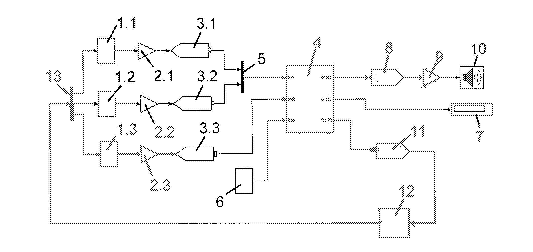
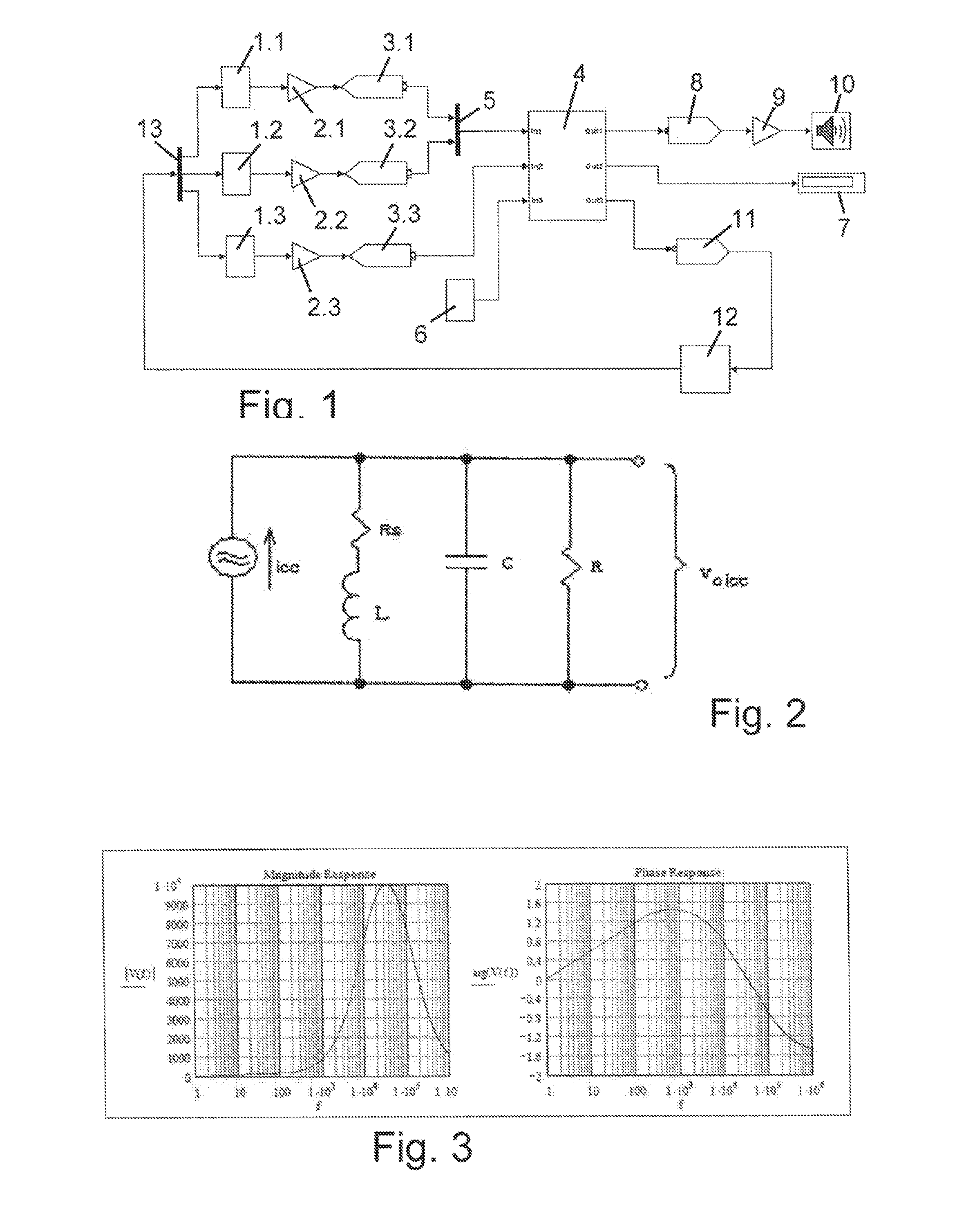
[0036]Referring firstly to FIG. 1, the main components of the cable locator are shown by way of example, but it will be appreciated that detection apparatus in accordance with some embodiments of the invention may include additional features and components, for example a GPS receiver. In this example the cable locator has three magnetic sensors 1.1, 1.2 and 1.3 in the form of conventional low frequency ferrite-cored antennas designed for maximum sensitivity and low noise. The signals from the windings of the three antennas are sent to respective pre-amplifiers 2.1, 2.2 and 2.3 which (i) ensure that the sensor noise dominates the ADC quantization noise by about +6 dB, and (ii) have a transfer function which normalizes the antenna response as a functi...


PUM


Abstract

A detection apparatus with a self-test is presented. A detection apparatus such as a cable locator has an array of sensors in the form of ferrite antennas to detect an electromagnetic field produced by an object such as a buried cable. The signals are amplified, digitized and fed to a processing unit that outputs a detection signal to a display to indicate the detection of a cable. A programmable signal generator outputs a self-test signal via a voltage-current converter that is used to check the balance between the sensors. The self-test signal is directly coupled into each of the sensors through a wired connection and the processing unit uses the self-test signal to accurately determine the magnitude and phase balance of the sensors. The magnitude and phase data may be used to calibrate the instrument, apply data corrections or flag errors.

Description

RELATED APPLICATIONS[0001]The present application claims priority to Great Britain Application No. GB 14 02 952.4, filed on Feb. 19, 2014, which is herein incorporated by reference in its entirety.BACKGROUND[0002]1. Technical Field[0003]This disclosure is concerned with improving the integrity and accuracy of detection apparatus, for example a cable locating instrument, which senses low frequency electromagnetic signals.[0004]2. Discussion of Related Art[0005]A cable locating instrument typically uses an array of sensors, arranged in a fixed geometry, to derive information about the relative direction of a buried utility. Low frequency magnetic sensors are a popular choice and work well when used in conjunction with a current source, which is connected to the utility.[0006]A typical sensor uses a coil of wire wound on a ferrite core and is often referred to as an antenna. With such an antenna, it is possible to measure the magnetic field in one direction only or, by using a spatial ...

Claims


Application Information

Patent Timeline
IPC IPC(8): G01R35/00
CPCG01R35/00G01R29/0814G01V3/08G01V13/00G01R29/085G01R33/0041G01R35/005
Inventor POLAK, STEVAN
Owner BUSAN TRANSPORTATION CORPORATION
Why Eureka
Try Eureka