Apparatus and method for localized irrigation and application of fertilizers, herbicides, or pesticides to row crops

a technology of applicator and irrigation method, applied in the field of agricultural equipment, can solve the problems of unsatisfactory results of speeding up the process by utilizing faster tractor speed and employing electronically controlled irrigation valves, unavoidable damage to plants and topsoil, and use of automated irrigation technology, so as to reduce the hydrostatic pressure and velocity of the aqueous solution

Inactive Publication Date: 2015-08-27
CELLI ROBERT +1
View PDF0 Cites 23 Cited by
  • Summary
  • Abstract
  • Description
  • Claims
  • Application Information

AI Technical Summary

Benefits of technology

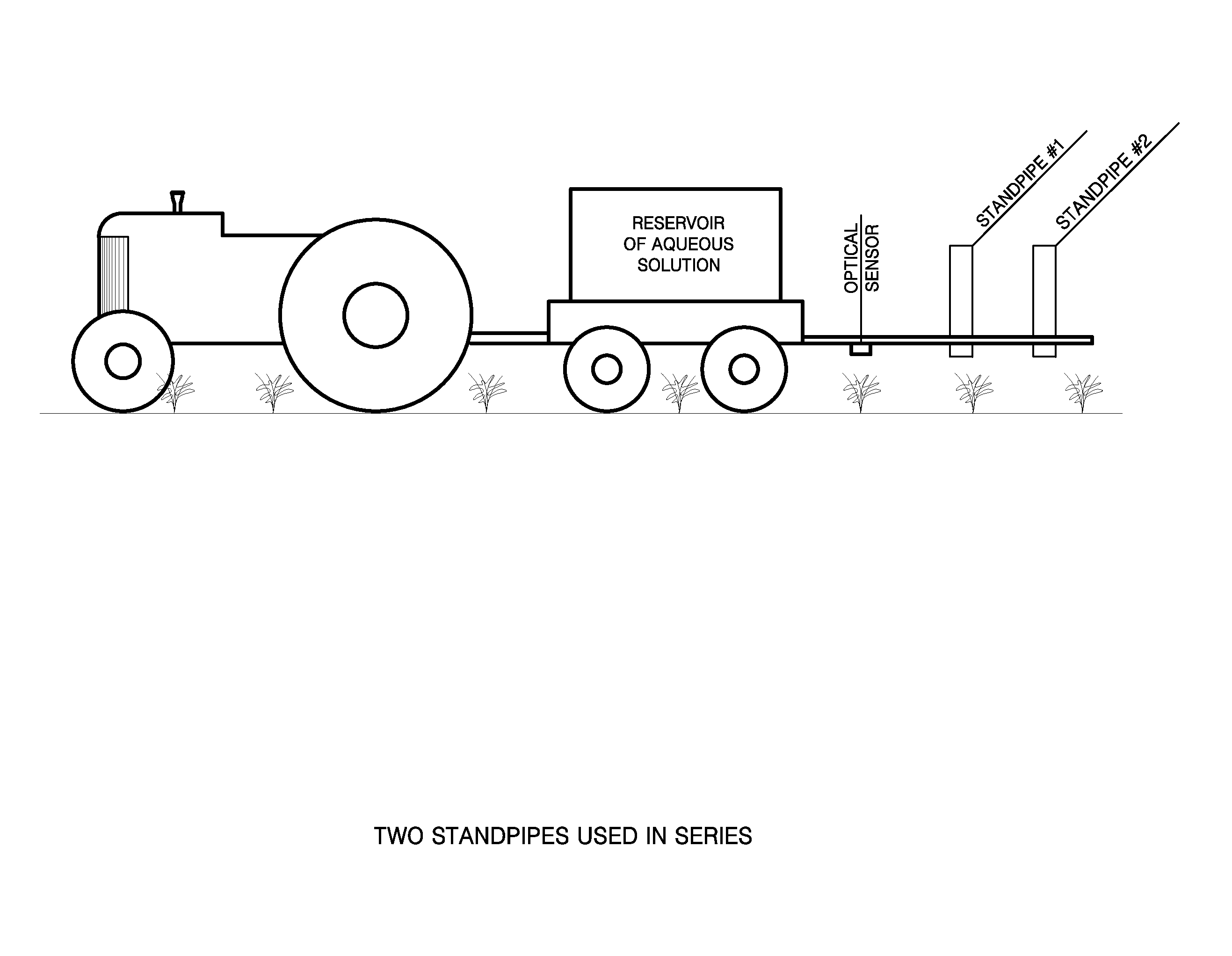
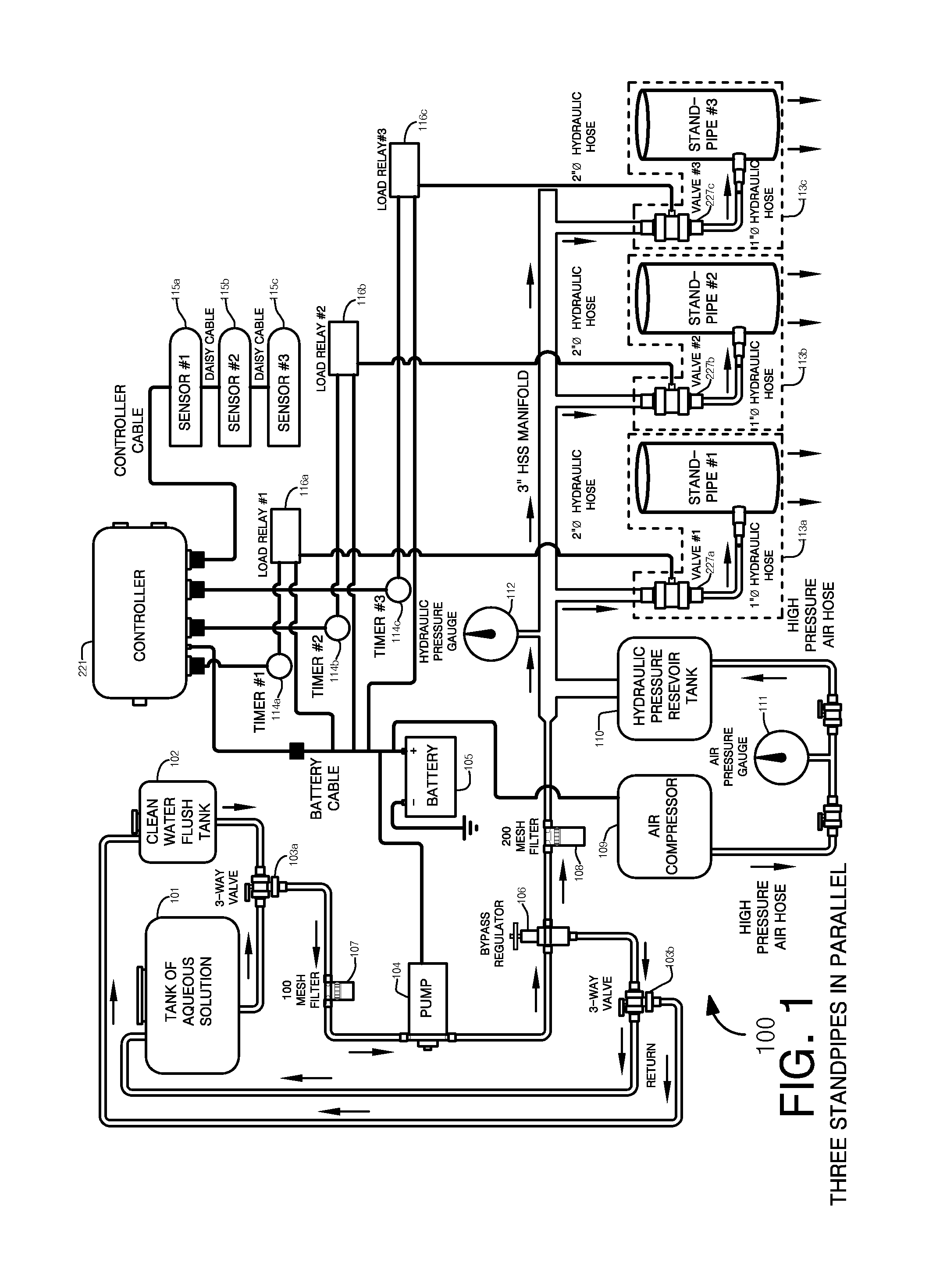
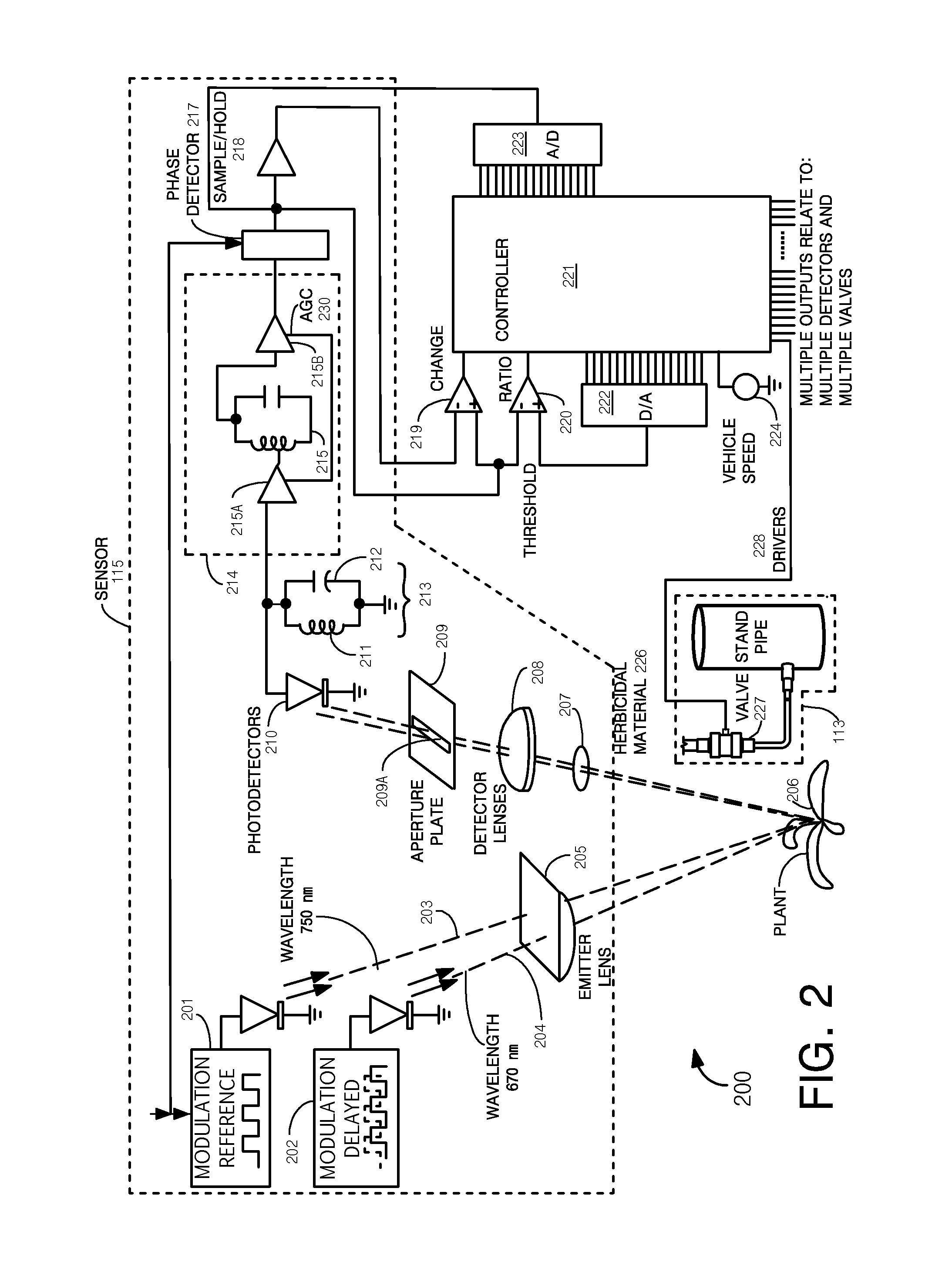
[0023]In a further embodiment, the present invention provides a method of electronically and rapidly delivering an aqueous solution to a localized annulus of ground surrounding a plant, the method comprising the steps of (a) pumping the aqueous solution from a tank through a first pipe; (b) reducing the hydrostatic pressure and velocity of the aqueous solution by continuing to flow the aqueous solution into a second pipe having a greater diameter than the first pipe; (c) maintaining laminar flow of the aqueous solution simultaneously with step (b); (d) streaming a plurality of aliquots of the aqueous solution in an upward direction from the output of the second pipe into the center of) a standpipe; (e) terminating the streaming of step (d); and (f) delivering the aqueous solution at a low velocity from the standpipe to the target area with a specified wetting pattern.

Problems solved by technology

Attempts to speed up the process by utilizing faster tractor speeds and employing electronically controlled irrigation valves have not produced satisfactory results because faster tractor speeds require higher flow rates which cause damage when applied directly to individual plants during a brief period of time.
The limiting factor in the use of automated irrigation technology has been the unavoidable damage to the plants and topsoil due to the intermittent high velocity flows emanating from high-pressure irrigation apparati.
Put simply, high velocity flow damages fragile vegetative structures and causes local soil erosion.
The use of a bucket or watering can is impractical for watering row crops at high production rates because the cycle time between adjacent plants encountered as the tractor traverses row crops at high speeds is shorter than the cycle time for periodic filling plus emptying of a bucket or watering can.
The result is: (i) an uneven distribution of water and fertilizers and herbicides and pesticides; (ii) application onto bare ground where it is useless and contributes to soil erosion and scour; (iii) some plants are missed altogether whilst others are sprayed twice; (iv) ineffective use of fertilizers, herbicides and pesticides; (v) overspray that can adversely affect the health of farm workers; and (vi) uneconomical use of increasingly expensive farm labor.
However, when irrigation is applied in such a manner, most of the effluent is wasted because it is deposited on vacant ground where the nutritional or medicinal additives have no effect.
Moreover, fertilizers, pesticides and herbicides may have highly undesirable effects on the environment, for example, by causing contamination of ground water or causing chemical burning of different crops in adjacent fields during floods.
However, many of these methods use devices that rely on natural sunlight to create a reflected image.
Thus, the devices cannot operate at night, and are seriously impaired under cloudy conditions, or even when operated in shadows.
However, under normal (i.e. sunny) operating conditions, this artificial light source must compete with the sun that is thousands of times brighter and constantly changing in brightness and spectral distribution.
Therefore, either method (i.e., using natural sunlight or an artificial white light source) fails to reliably provide an accurate wavelength signature of objects in the field of view of the device sufficient to optically recognize all individual plants within the visual field of the optical sensor.
Indeed, applications for these methods have been limited to low-till or no-till field crops where this lack of precision can be tolerated.
The use of optical control apparati has not been practical in controlling irrigation apparati because the output from optical control apparati is low voltage and low amperage electrical power.
The primary difficulty with such irrigation methods is that they necessarily rely upon intermittent high velocity flows.
An intermittent high-velocity flow results in unwanted soil erosion and is likely to result in structural damage to delicate nascent plants.

Method used


Image

  • Apparatus and method for localized irrigation and application of fertilizers, herbicides, or pesticides to row crops
  • Apparatus and method for localized irrigation and application of fertilizers, herbicides, or pesticides to row crops
  • Apparatus and method for localized irrigation and application of fertilizers, herbicides, or pesticides to row crops

Examples


Embodiment Construction

[0089]The present method of delivery of solution to row crops accommodates the need for greater tractor speed, predetermined aqueous solution volumes, low flow velocities of effluent delivered to individual plants, localization of the deposition, and rapid cycle times. The invention is directed to an apparatus and a method for selectively providing delicate nascent plants with a predetermined volume of aqueous solution. In one embodiment, the hydraulic apparatus, together with certain electronic controls, delivers aliquots of aqueous solution rapidly, yet under low pressure, thereby ensuring that delicate nascent plants are not damaged by high-pressure flows and also ensuring that bare soil is not subject to erosion. The on / off control of the hydraulic apparatus is provided by means of light emitters described herein. The streaming of the aliquots along the approximate center is still effective in the present invention, while a variation of approximately 10% from true center achieve...


PUM

PropertyMeasurementUnit
muzzle velocityaaaaaaaaaa
wavelengthaaaaaaaaaa

Abstract

An apparatus and method are provided for selectively providing delicate nascent plants with a predetermined volume of water containing fertilizer, pesticide, or herbicide to row crops in agriculture operations. The hydraulic apparatus, together with certain electronic controls, delivers aliquots of aqueous solution rapidly, yet under low pressure, thereby ensuring that delicate nascent plants are not damaged by high-pressure flows and also ensuring that bare soil is not subject to erosion. The on/off control of the hydraulic apparatus is provided by means of light emitters.

Description

CROSS-REFERENCE TO RELATED APPLICATIONS[0001]This application claims the benefit of U.S. Provisional Application No. 61 / 966,463, filed Feb. 24, 2014.FIELD OF THE INVENTION[0002]The present invention relates in general to agricultural equipment. In particular, the present invention relates to an apparatus and a method for selectively providing delicate nascent plants with a predetermined volume of water containing fertilizer, pesticide, or herbicide to row crops in agriculture operations.BACKGROUND OF THE INVENTION[0003]The following description is not an admission that any of the information provided herein is prior art or relevant to the present invention, or that any publication specifically or implicitly referenced is prior art. Any publications cited in this description are incorporated by reference herein. Where a definition or use of a term in an incorporated reference is inconsistent or contrary to the definition of that term provided herein, the definition of that term provi...

Claims


Application Information

Patent Timeline
Patent Type & Authority Applications(United States)
IPC IPC(8): A01C23/00G01N21/27A01G25/16G01N33/24A01G25/00A01C23/04
CPCA01C23/007A01G25/00A01C23/047G01N2033/245G01N33/24G01N21/27A01G25/16G01N21/31G01N21/35Y10T137/86027Y02P60/21A01G22/00
Inventor CELLI, ROBERTCELLI, JR., DAVID
Owner CELLI ROBERT
Why Eureka
Try Eureka