Devices, systems and methods for delivering a prosthetic mitral valve and anchoring device

a technology of which is applied in the field of devices, systems and methods for delivering prosthetic mitral valve and anchoring device, can solve the problems of mitral narrowing or stenosis, more difficult implantation of mitral valve, and death of heart failure, so as to improve the stability of the prosthesis

Active Publication Date: 2015-08-27
MITRAL VALVE TECHNOLOGIES SARL
View PDF2 Cites 238 Cited by
  • Summary
  • Abstract
  • Description
  • Claims
  • Application Information

AI Technical Summary

Benefits of technology

[0005]Previous filings (for example, International PCT Publication No. WO 2013 / 114214, the disclosure of which is hereby incorporated by reference herein) have provided a disclosure on the use of an anchor to attach a mitral valve prosthesis in a patient via a catheter or minimally invasive procedure. The anchor most commonly described in these disclosures is a helical anchor which is first placed near the native mitral valve annulus and then the prosthetic valve is implanted inside the anchor. It would also be possible to add a helical anchor after the prosthetic valve was placed. The helical anchor can be placed to improve the stability of the prosthesis, to prevent rocking or even to control a leak that occurs around the valve. Whether the anchor is placed before or after the valve implant, this creates a two-step procedure for the interventionalist. He or she must first place the anchor, and then place the prosthetic valve, or vice versa.

Problems solved by technology

Complications of the mitral valve, which controls the flow of blood from the left atrium into the left ventricle of the human heart, have been known to cause fatal heart failure.
In addition to mitral regurgitation, rheumatic disease can lead to mitral narrowing or stenosis.
In the course of the last decade many companies have been successful in creating catheter or minimally invasive implantable aortic valves, but such implantation of a mitral valve is more difficult.
Many patients who require mitral valve replacement are elderly and an open heart procedure is painful, risky and takes time for recovery.
Some patients are not even candidates for such a surgery due to their advanced age and frailty.

Method used


Image

  • Devices, systems and methods for delivering a prosthetic mitral valve and anchoring device
  • Devices, systems and methods for delivering a prosthetic mitral valve and anchoring device
  • Devices, systems and methods for delivering a prosthetic mitral valve and anchoring device

Examples


first embodiment

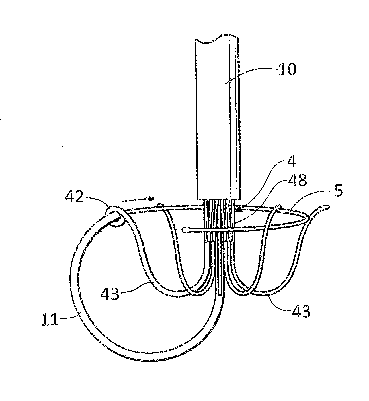
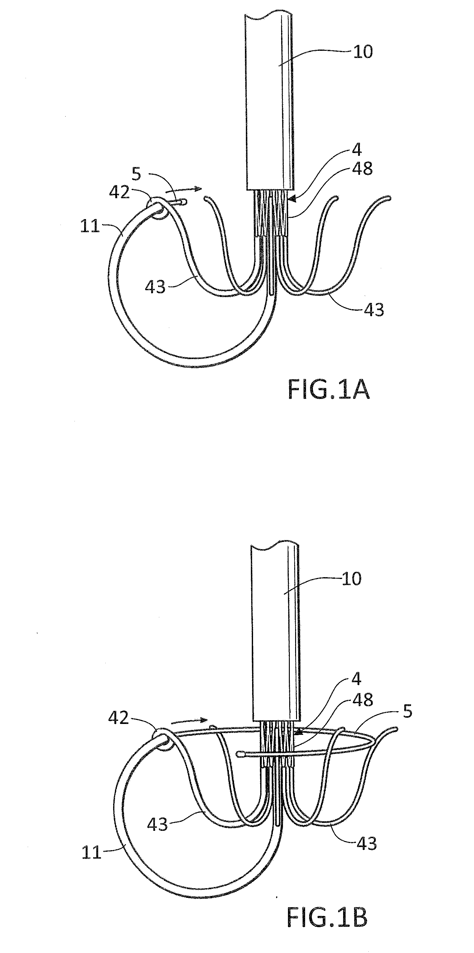
[0018]FIGS. 1A-1B show close-up perspective views of an end of a delivery catheter 10 from which a prosthetic valve 4 and a helical anchoring device 5 are being delivered, according to the invention. For clarity, structures of the heart have been omitted in these figures.

[0019]FIG. 1A shows the prosthetic valve 4 with a portion extending from the delivery catheter 10, and a portion that is still being held in the delivery catheter 10. The prosthetic valve 4 includes a valve frame 48 that is expandable from a collapsed position or configuration in which a diameter of the valve frame 48 is reduced to an expanded position or configuration in which the diameter of the valve frame 48 is increased. The valve frame 48 can be collapsed to facilitate delivery through the delivery catheter 10, and can be expanded during or after placement at a native mitral valve, in order to engage the mitral valve annulus or an anchoring device 5 placed at the mitral position, as will be discussed in greate...

second embodiment

[0055]FIGS. 3A-3B show the end of the delivery catheter 10 from which a prosthetic valve 4′ is being delivered, according to a For clarity, structures of the heart 2 have been omitted in these figures.

[0056]In the embodiments described above, the helical anchor delivery catheter 11 that delivers the helical anchoring device 5 under the native mitral leaflets 31 is separate from the prosthetic device 4. In the embodiment illustrated in FIGS. 3A-3B, the helical anchor delivery catheter has been incorporated into the prosthetic valve 4′ as a modified arm 43′. The prosthetic valve 4′ includes the modified arm 43′ that wraps around one of the mitral leaflets 31, similar to the other arms 43. Here, the modified arm 43′ is a hollow tube that can be loaded with the helical anchoring device 5, and which is sized so that the helical anchoring device can be advanced therethrough. The modified arm 43′ includes a bend 47 and a portion at a distal end that is angled relative to the rest of the a...


PUM


Abstract

Prosthetic mitral heart valves and anchors for use with such valves are provided that allow for an improved implantation procedure. In various embodiments, a helical anchoring device is formed as a coiled or twisted anchor that includes one or more turns that twist or curve around a central axis. Curved arms attached to the frame of the valve guide the helical anchoring device into position beneath the valve leaflets and around the mitral valve annulus as it exits the delivery catheter, and the expandable prosthetic mitral valve is held within the coil of the anchoring device. The anchoring device and the valve can be delivered together, simplifying the valve replacement procedure.

Description

CROSS-REFERENCE TO RELATED APPLICATION[0001]The present disclosure claims the benefit of U.S. Provisional Patent Application Ser. No. 61 / 943,125, filed Feb. 21, 2014, the contents of which are hereby incorporated by reference in their entirety.BACKGROUND FIELD[0002]Complications of the mitral valve, which controls the flow of blood from the left atrium into the left ventricle of the human heart, have been known to cause fatal heart failure. In the developed world, one of the most common forms of valvular heart disease is mitral valve leak, also known as mitral regurgitation, which is characterized by the abnormal leaking of blood from the left ventricle through the mitral valve and back into the left atrium. This occurs most commonly due to ischemic heart disease when the leaflets of the mitral valve no longer meet or close properly after multiple infarctions, idiopathic and hypertensive cardiomyopathies where the left ventricle enlarges, and with leaflet and chordal abnormalities, ...

Claims


Application Information

Patent Timeline
Patent Type & Authority Applications(United States)
IPC IPC(8): A61F2/24
CPCA61F2/2418A61F2230/0069A61F2/2412A61F2/2427A61F2/2436A61F2230/0091A61F2250/006
Inventor SPENCE, PAUL A.TOMPKINS, LANDON H.
Owner MITRAL VALVE TECHNOLOGIES SARL
Why Eureka
Try Eureka