Methods and Techniques to use with Photosensitized Chemically Amplified Resist Chemicals and Processes

a chemical and amplified resist technology, applied in the field of methods and techniques to use with photosensitized chemically amplified resist chemicals and processes, can solve the problems of euv shot noise, non-optimum line width roughness (lwr), ler, and cwr depending, and achieves the effect of increasing chemical reactions, maximizing absorbance, and improving acid generation

Active Publication Date: 2015-08-27
TOKYO ELECTRON LTD
View PDF31 Cites 25 Cited by
  • Summary
  • Abstract
  • Description
  • Claims
  • Application Information

AI Technical Summary

Benefits of technology

[0004]One concern with using a PS-CAR may be reflectivity and absorption control associated with the exposure steps that may be exposed to the resist. In one embodiment, reflectivity and absorption control may be addressed by tailoring the film layer under (e.g., underlayer (UL)) the typical photoresist to have either minimal or no reflections during the flood exposure. This may be accomplished by using a material that has high absorption of the flood wavelength(s). For example, the index of refraction differences between the resist layer and the UL may be used to tailor the highest intensity from the interference of the incoming light and the reflected flood light to be preferentially located in the resist layer (e.g. near resist / UL interface) as a way to prevent micro-bridging and / or scumming or as a way to have some tailored resist profile control when the resist is developed.
[0005]In another embodiment, one or more top coat layers may be deposited on the resist to optimize PAG decomposition. The top coat layer(s) may be designed for outgassing and out-of-band (OOB) radiation control. For example, in the EUV / UV exposure process, it may be desirable to prevent inadvertent PAG decomposition by EUV OOB radiation (˜248 nm) but allow the UV flood target exposure wavelengths to excite the PS. In one specific embodiment, a first top coat may be deposited on the photoresist prior to the first exposure. The first top coat may be removed from the substrate and a second top coat layer may be deposited on the photoresist layer prior to the flood exposure. In another embodiment, the top coat layer may be applied prior to the first exposure and remove before the second exposure. A second top coat layer does not need to be applied prior to the second exposure.
[0006]A second concern for the PS-CAR concept may be related to the EUV shot noise effect when the PS-CAR concept is pushed to its extremes of low EUV dose exposure. Pushing EUV exposure dose to its minimum limits, a photon / secondary electron shot statistics problem, known as EUV shot noise, may be present. Since the photosensitizer is created in close proximity to any acids converted from PAGs, the photosensitizer will largely replicate the issue and thus have a photosensitizer concentration shot noise effect. Without smoothing of the photosensitizer concentration shot noise prior to or in-situ to UV flood excitation, the photosensitizer concentration shot noise will likely lead to non-optimum line width roughness (LWR), LER, and CWR depending on feature type. Incorporating a bake step prior to UV flood step to induce photosensitizer diffusion, on the order sub 10 nm, may smooth out the photosensitizer concentration shot noise and lead to better LWR, LER and or CER.

Problems solved by technology

Pushing EUV exposure dose to its minimum limits, a photon / secondary electron shot statistics problem, known as EUV shot noise, may be present.
Without smoothing of the photosensitizer concentration shot noise prior to or in-situ to UV flood excitation, the photosensitizer concentration shot noise will likely lead to non-optimum line width roughness (LWR), LER, and CWR depending on feature type.

Method used


Image

  • Methods and Techniques to use with Photosensitized Chemically Amplified Resist Chemicals and Processes
  • Methods and Techniques to use with Photosensitized Chemically Amplified Resist Chemicals and Processes
  • Methods and Techniques to use with Photosensitized Chemically Amplified Resist Chemicals and Processes

Examples


Embodiment Construction

[0012]Although the present invention will be described with reference to the embodiments shown in the drawings, it should be understood that the present invention can be embodied in many alternate forms of embodiments. In addition, any suitable size, shape or type of elements or materials could be used.

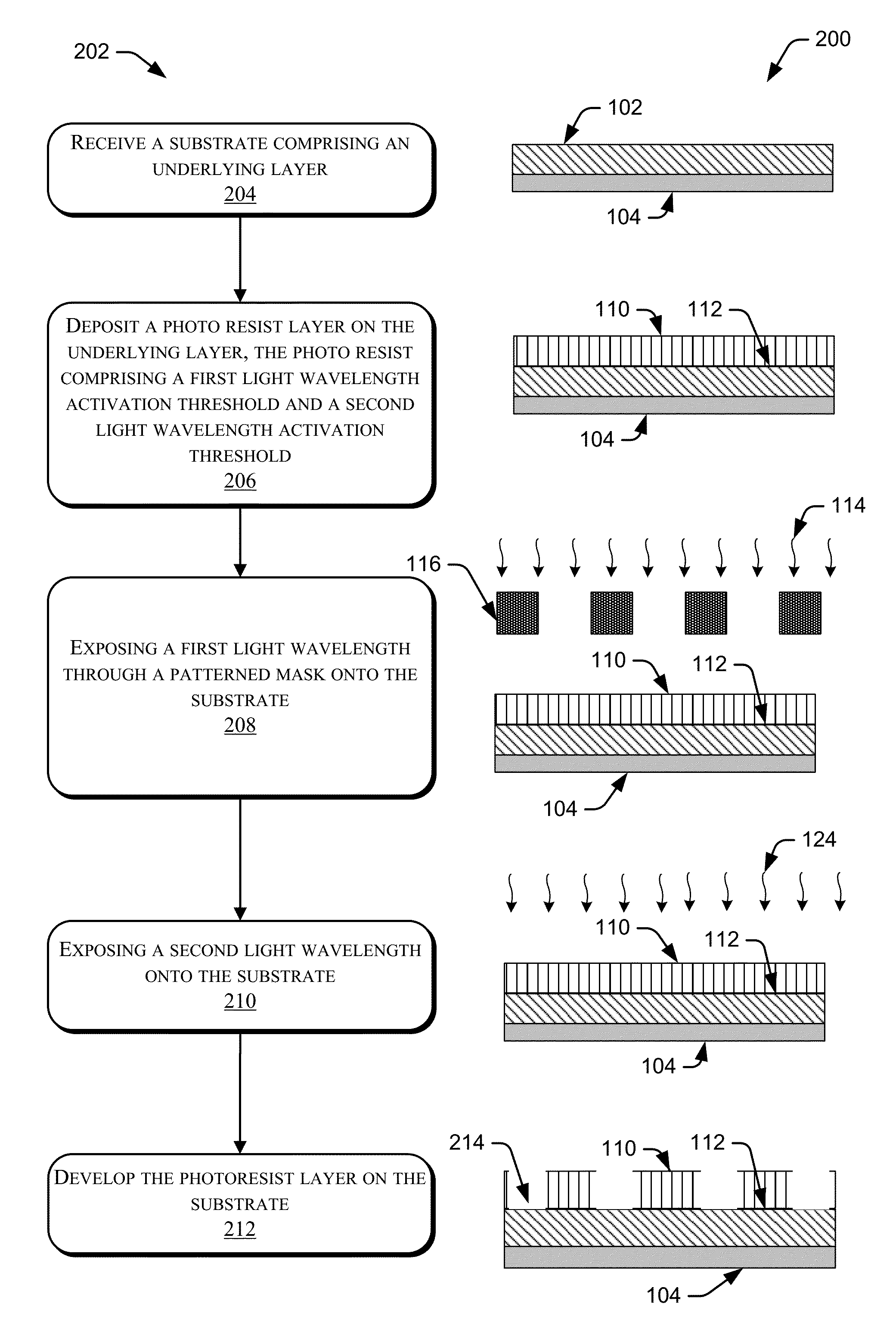
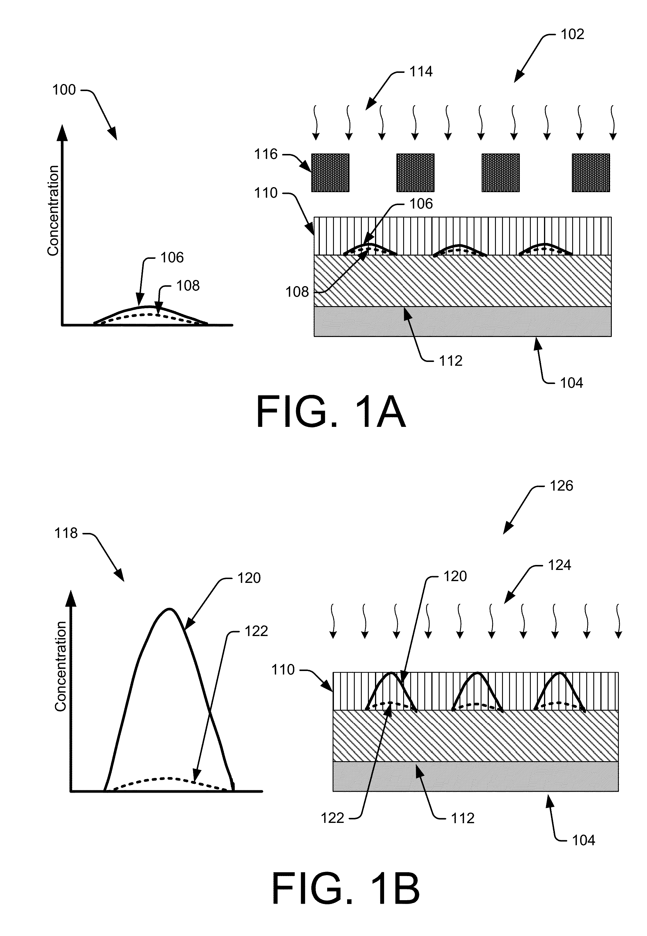
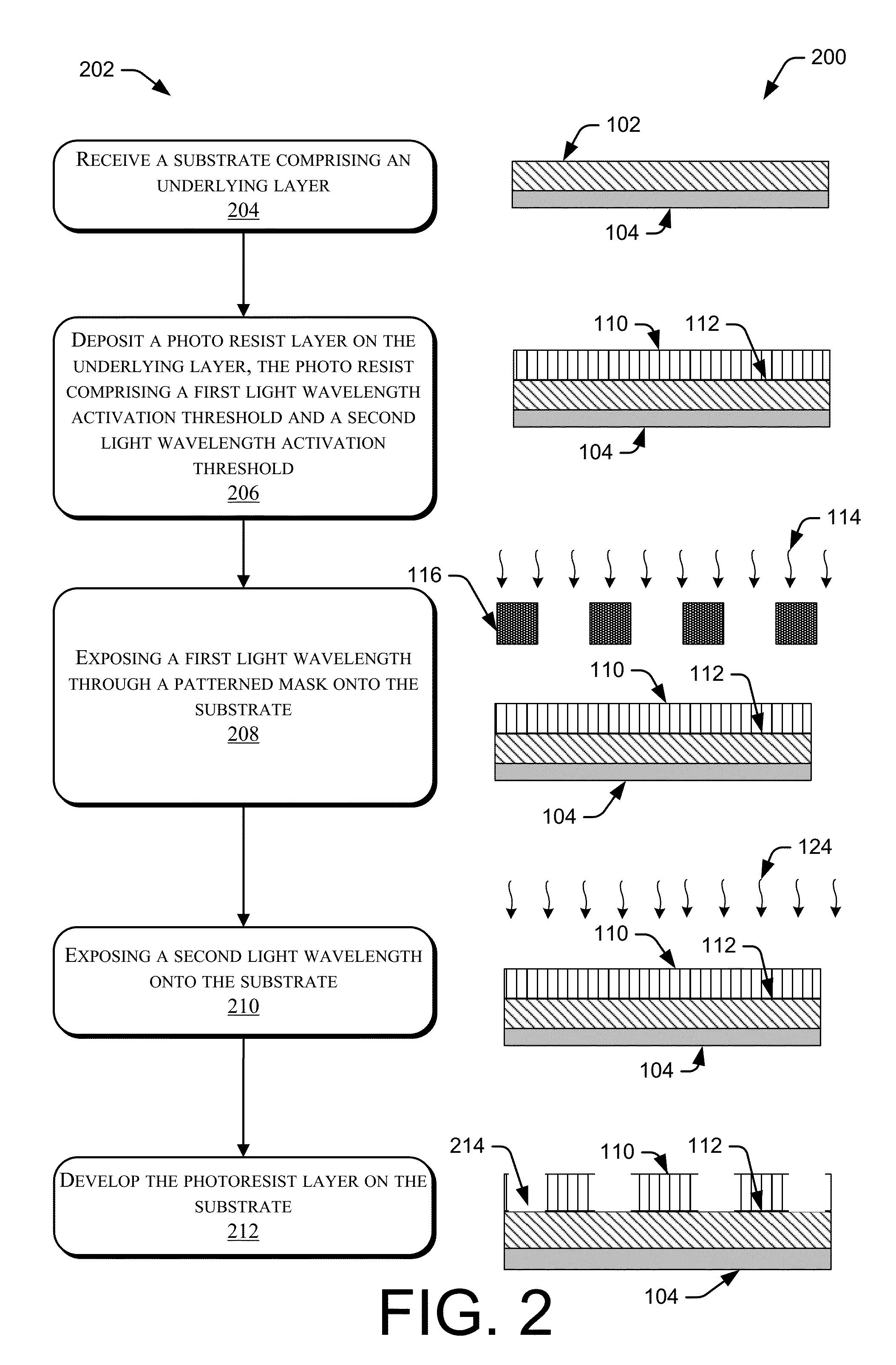
[0013]In semiconductor manufacturing, photoresist or light sensitive materials have been used to manufacture electronic devices by depositing, patterning, and etching films on a substrate. Shrinking the dimensions of the electronic devices and maintaining image quality (e.g., resolution, line width roughness, and sensitivity) to improve device performance and yield. Extreme Ultraviolet (EUV) photolithography is one approach to shrinking dimensions that has inherent limitations that may impact existing photoresist chemistries. For example, EUV photoresist may need to compensate for the lower power of EUV light sources while maintaining resist sensitivity and image resolution. One appro...


PUM

PropertyMeasurementUnit
thicknessaaaaaaaaaa
thicknessaaaaaaaaaa
wavelengthaaaaaaaaaa

Abstract

The disclosure herein describes methods for Photosensitized Chemically Amplified Resist Chemicals (PS-CAR) to pattern light sensitive films on a semiconductor substrate. In one embodiment, a two-step exposure process may generate higher acid concentration regions within a photoresist layer. The PS-CAR chemicals may include photoacid generators (PAGs) and photosensitizer elements that enhance the decomposition of the PAGs into acid. The first exposure may be a patterned EUV exposure that generates an initial amount of acid and photosensitizer. The second exposure may be a non-EUV flood exposure that excites the photosensitizer which increases the acid generation rate where the photosensitizer is located on the substrate. The distribution of energy during the exposures may be optimized by using certain characteristics (e.g., thickness, index of refraction, doping) of the photoresist layer, an underlying layer, and / or an overlying layer.

Description

CROSS REFERENCE TO RELATED APPLICATIONS[0001]The present application claims the benefit of U.S. Provisional Patent Application No. 61 / 944,041, filed on Feb. 24, 2014, entitled “Methods and Techniques to use with Photosensitized Chemically Amplified Resist Chemicals and Processes,” which is incorporated herein by reference in its entirety.BACKGROUND OF THE INVENTION[0002]Critical dimension (CD) control for photolithography patterning is important for semiconductor device manufacturing. One aspect of patterning includes generating patterns on photosensitive materials may be imparted to underlying layers or the substrate by subsequent processing. However, the quality of the overlying patterns has a strong impact on the quality of the patterns on the underlying layers. Also, as CDs scale to smaller dimensions, patterning processes have incorporated smaller wavelengths of light that may not have as many photons as the larger light wavelengths. As a result, the amount of acid generated wi...

Claims


Application Information

Patent Timeline
Patent Type & Authority Applications(United States)
IPC IPC(8): G03F7/20G03F7/09G03F7/30H01L21/027
CPCG03F7/2024H01L21/0274G03F7/2002G03F7/30G03F7/09H01L21/0271H01L21/0276G03F7/0045G03F7/2022G03F7/091G03F7/0382G03F7/0392G03F7/11G03F7/2004G03F7/26G03F7/38
Inventor CARCASI, MICHAEL A.HOOGE, JOSHUA S.RATHSACK, BENJAMEN M.NAGAHARA, SEIJI
Owner TOKYO ELECTRON LTD
Why Eureka
Try Eureka